Panasonic D10000U Operating Instructions - Page 24
Connection - manual
 |
UPC - 791871111413
View all Panasonic D10000U manuals
Add to My Manuals
Save this manual to your list of manuals |
Page 24 highlights
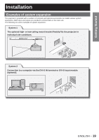
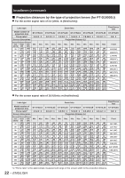
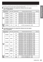
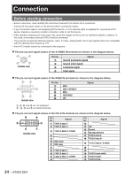
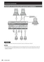
Connection Before starting connection • Before connection, read carefully the instruction manual for the device to be connected. • Turning off the power switch of the devices before connecting cables. • If any connection cable is not supplied with the device, or if no optional cable is available for connection of the device, prepare a necessary system connection cable to suit the device. • Video signals containing too much jitter may cause the images on the screen to randomly wobble or wafture. In this case, a time base corrector (TBC) must be connected. • The projector accepts the following signals: video, S-Video, analog RGB, DVI-D and signals which are compatible with the optional input module (p. 27). • Some PC models cannot be connected to the projector. ● The pin-out and signal names of the S-VIDEO IN terminal are shown in the diagram below. Outside view Pin No. # $ % & Signal Ground (luminance signal) Ground (color signal) Luminance signal Color signal ● The pin-out and signal names of the RGB2 IN terminal are shown in the diagram below. Outside view Pin No. # $ % 1 2 R/PR G/G • SYNC/Y B/PB HD/SYNC VD Signal &, -, 0, and 3 are not assigned. ( - +, . and / are GND terminals. ● The pin-out and signal names of the DVI-D IN terminal are shown in the diagram below. = 5 4 - + # Outside view Pin No. Signal # T.M.D.S data 2- $ T.M.D.S data 2+ % T.M.D.S data 2 / 4 shield & ( ) DDC clock * DDC data + - T.M.D.S data 1- . T.M.D.S data 1+ / T.M.D.S data 1 / 3 shield 0 Pin No. Signal 1 2 +5V 3 Ground 4 Hot plug detection 5 T.M.D.S data 0- 6 T.M.D.S data 0+ 7 T.M.D.S data 0 / 5 shield 8 9 : T.M.D.S clock shield ; T.M.D.S clock+ = T.M.D.S clock- 24 - ENGLISH
-
 1
1 -
2
-
3
-
4
-
5
-
6
-
7
-
8
-
9
-
10
-
11
-
12
-
13
-
14
-
15
-
16
-
17
-
18
-
 19
19 -
 20
20 -
 21
21 -
 22
22 -
 23
23 -
 24
24 -
 25
25 -
 26
26 -
 27
27 -
 28
28 -
 29
29 -
30
-
31
-
32
-
33
-
34
-
35
-
36
-
37
-
38
-
39
-
40
-
41
-
42
-
43
-
44
-
45
-
46
-
47
-
48
-
49
-
50
-
51
-
52
-
53
-
54
-
55
-
56
-
57
-
58
-
59
-
60
-
61
-
62
-
63
-
64
-
65
-
66
-
67
-
68
-
69
-
70
-
71
-
72
-
73
-
74
-
75
-
76
-
77
-
78
-
79
-
80
-
81
-
82
-
83
-
84
-
85
-
86
-
87
-
88
-
89
-
90
-
91
-
92
-
93
-
94
-
95
-
96
-
97
-
98
-
99
-
100
-
101
-
102
-
103
-
104
-
105
-
106
-
107
-
108
-
109
-
110
-
111
-
112
-
113
-
114
-
115
-
116
-
117
-
118
-
119
-
120
-
121
-
122
-
123
-
124
-
125
-
126
-
127
-
128
-
129
-
130
-
131
-
132
 |
 |
