Panasonic D10000U Operating Instructions - Page 25
Getting Started, Example of, connecting with VIDEO devices
 |
UPC - 791871111413
View all Panasonic D10000U manuals
Add to My Manuals
Save this manual to your list of manuals |
Page 25 highlights
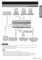
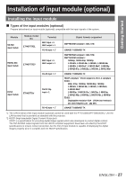
Getting Started Example of connecting with VIDEO devices Control PC Control PC Control PC Video deck (TBC built-in) IN OUT REMOTE 1 REMOTE 2 IN RS-232C IN RS-422 IN SERIAL RS-422 OUT LAN IN OUT VIDEO S-VIDEO IN R/PR G/Y SYNC/HD RGB 1 IN B/PB VD RGB 2 IN DVI-D IN Red (connected to PR terminal) Blue (connected to PB terminal) Green (connected to Y terminal) Color monitor Video deck (TBC built-in) High-vision video deck DVD player with HDMI (HDCP) terminal Attention • When connecting with a video deck, be sure to use the one with a built-in time base corrector (TBC) or use a TBC between the projector and the video deck. • If nonstandard burst signals are connected, the image may be distorted. If this is the case, connect a TBC between the projector and the video deck. Note • The DVI-D signal input terminal supports only a single link. • The HDMI-DVI-D conversion cable is required to connect an HDMI-compliant device. • The EDID mode setting must be selected so that it corresponds to the device to be connected. (pp. 71, 72) • It is possible to connect the DVI-D input terminal with an HDMI- or DVI-D-compliant device, but with some devices the images may not appear or other problems may be encountered in operation. ENGLISH - 25
-
 1
1 -
2
-
3
-
4
-
5
-
6
-
7
-
8
-
9
-
10
-
11
-
12
-
13
-
14
-
15
-
16
-
17
-
18
-
19
-
 20
20 -
 21
21 -
 22
22 -
 23
23 -
 24
24 -
 25
25 -
 26
26 -
 27
27 -
 28
28 -
 29
29 -
 30
30 -
31
-
32
-
33
-
34
-
35
-
36
-
37
-
38
-
39
-
40
-
41
-
42
-
43
-
44
-
45
-
46
-
47
-
48
-
49
-
50
-
51
-
52
-
53
-
54
-
55
-
56
-
57
-
58
-
59
-
60
-
61
-
62
-
63
-
64
-
65
-
66
-
67
-
68
-
69
-
70
-
71
-
72
-
73
-
74
-
75
-
76
-
77
-
78
-
79
-
80
-
81
-
82
-
83
-
84
-
85
-
86
-
87
-
88
-
89
-
90
-
91
-
92
-
93
-
94
-
95
-
96
-
97
-
98
-
99
-
100
-
101
-
102
-
103
-
104
-
105
-
106
-
107
-
108
-
109
-
110
-
111
-
112
-
113
-
114
-
115
-
116
-
117
-
118
-
119
-
120
-
121
-
122
-
123
-
124
-
125
-
126
-
127
-
128
-
129
-
130
-
131
-
132
 |
 |
