Pioneer AVH-4200NEX Owner s Manual - Page 58
Notice for the blue/white lead, Rear panel main terminals, Power cord
 |
View all Pioneer AVH-4200NEX manuals
Add to My Manuals
Save this manual to your list of manuals |
Page 58 highlights
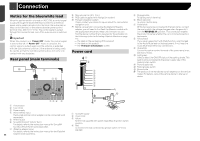
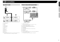
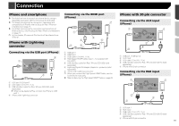
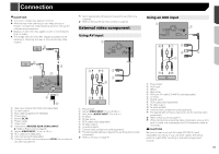
Connection Notice for the blue/white lead When the ignition switch is turned on (ACC ON), a control signal is output through the blue/white lead. Connect to an external power amp's system remote control terminal, the auto-antenna relay control terminal, or the antenna booster power control terminal (max. 300 mA 12 V DC). The control signal is output through the blue/white lead, even if the audio source is switched off. Important When this product is in "Power OFF" mode, the control signal is also turned off. If "Power OFF" mode is canceled, the control signal is output again and the antenna is extended with the auto antenna function (if the antenna is being used). Be careful so that the extended antenna does not come into contact with any obstacles. Rear panel (main terminals) a 9 8 76 1 23 4 5 1 This product 2 Fuse (10 A) 3 Power supply 4 Wired remote input Hard-wired remote control adapter can be connected (sold separately). 5 Antenna jack 6 SiriusXM Connect Vehicle Tuner For details, refer to the instruction manual for SiriusXM Connect Vehicle Tuner (sold separately). 7 iDatalink adapter input For details, refer to the instruction manual for the iDatalink 58 adapter (sold separately). 8 Microphone 3 m (9 ft. 10 in.) 9 RGB cable (supplied with Navigation system) a Pioneer navigation system Please contact your dealer to inquire about the connectable navigation unit. p Before using and/or connecting the iDatalink Maestro adapter, you will need to first flash the Maestro module with the appropriate vehicle and head unit firmware. You can find the device number that is required for the activation on the followings (refer to Activating iDatalink Maestro on page 44): - the label on the packaging of this product - the label on this product - the "Firmware Information" screen Power cord 1 2 3 4 5 6 7 8 9 a c b d 1 To power supply 2 Power cord 3 Yellow To terminal supplied with power regardless of ignition switch position. 4 Red To electric terminal controlled by ignition switch (12 V DC) ON/OFF. 5 Orange/white To lighting switch terminal. 6 Black (ground) To vehicle (metal) body. 7 Violet/white Of the two lead wires connected to the back lamp, connect the one in which the voltage changes when the gear shift is in the REVERSE (R) position. This connection enables the product to sense whether the car is moving forwards or backwards. 8 Yellow/black If you use an equipment with Mute function, wire this lead to the Audio Mute lead on that equipment. If not, keep the Audio Mute lead free of any connections. 9 Blue/white Connect to system control terminal of the power amp (max. 300 mA 12 V DC). a Light green Used to detect the ON/OFF status of the parking brake. This lead must be connected to the power supply side of the parking brake switch. b Power supply side c Parking brake switch d Ground side p The position of the handbrake switch depends on the vehicle model. For details, consult the vehicle Owner's Manual or dealer.
-
 1
1 -
2
-
3
-
4
-
5
-
6
-
7
-
8
-
9
-
10
-
11
-
12
-
13
-
14
-
15
-
16
-
17
-
18
-
19
-
20
-
21
-
22
-
23
-
24
-
25
-
26
-
27
-
28
-
29
-
30
-
31
-
32
-
33
-
34
-
35
-
36
-
37
-
38
-
39
-
40
-
41
-
42
-
43
-
44
-
45
-
46
-
47
-
48
-
49
-
50
-
51
-
52
-
 53
53 -
 54
54 -
 55
55 -
 56
56 -
 57
57 -
 58
58 -
 59
59 -
 60
60 -
 61
61 -
 62
62 -
 63
63 -
64
-
65
-
66
-
67
-
68
-
69
-
70
-
71
-
72
-
73
-
74
-
75
-
76
-
77
-
78
-
79
-
80
-
81
-
82
-
83
-
84
-
85
-
86
-
87
-
88
-
89
-
90
-
91
-
92
-
93
-
94
-
95
-
96
-
97
-
98
-
99
-
100
-
101
-
102
-
103
-
104
-
105
-
106
-
107
-
108
-
109
-
110
-
111
-
112
-
113
-
114
-
115
-
116
-
117
-
118
-
119
-
120
-
121
-
122
-
123
-
124
-
125
-
126
-
127
-
128
-
129
-
130
-
131
-
132
-
133
-
134
-
135
-
136
-
137
-
138
-
139
-
140
-
141
-
142
-
143
-
144
-
145
-
146
-
147
-
148
-
149
-
150
-
151
-
152
-
153
-
154
-
155
-
156
-
157
-
158
-
159
-
160
-
161
-
162
-
163
-
164
-
165
-
166
-
167
-
168
-
169
-
170
-
171
-
172
-
173
-
174
-
175
-
176
-
177
-
178
-
179
-
180
-
181
-
182
-
183
-
184
-
185
-
186
-
187
-
188
-
189
-
190
-
191
-
192
-
193
-
194
-
195
-
196
-
197
-
198
-
199
-
200
-
201
-
202
-
203
-
204
-
205
-
206
-
207
-
208
-
209
-
210
-
211
-
212
-
213
-
214
-
215
-
216
-
217
-
218
-
219
-
220
-
221
-
222
-
223
-
224
-
225
-
226
-
227
-
228
-
229
-
230
-
231
-
232
-
233
-
234
-
235
-
236
-
237
-
238
-
239
-
240
-
241
-
242
-
243
-
244
 |
 |
