Sony CPD-G200 Operating Instructions (primary manual) - Page 5
Cdoc06
 |
View all Sony CPD-G200 manuals
Add to My Manuals
Save this manual to your list of manuals |
Page 5 highlights
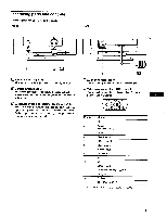
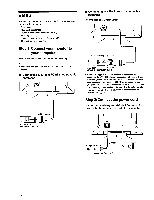
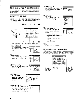
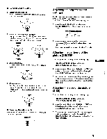
Identifying parts and controls See the pages in parentheses for further details. Front V CM> Rear OC M RESET button (page 12) This button resets the adjustments to the factory settings. Control button (page 9) The control button is used to display the menu and make adjustments to the monitor, including brightness and contrast adjustments. E] 6 (power) switch and indicator (pages 7, 13, 16) This button turns the monitor on and off. The power indicator lights up in green when the monitor is turned on, and either flashes in green and orange, or lights up in orange when the monitor is in power saving mode. [4 -5] ill AC IN connector (page 6) This connector provides AC power to the monitor. M Video input connector (HD15) (page 6) This connector inputs RGB video signals (0.700 Vp-p, positive) and sync signals. ® 00 ®C)) ,CDOC)06 00006 Pin No. 1 2 3 4 5 6 7 8 9 10 11 12 13 14 15 Signal Red Green (Sync on Green) Blue LD (Ground) DDC Ground* Red Ground Green Ground Blue Ground Ground II) (Ground) Bi-Directional Data (SDA)* H. Sync V. Sync Data Clock (SCL)* * DDC (Display Data Channel) is a standard of VESA. 5
-
 1
1 -
 2
2 -
 3
3 -
 4
4 -
 5
5 -
 6
6 -
 7
7 -
 8
8 -
 9
9 -
 10
10 -
 11
11 -
12
-
13
-
14
-
15
-
16
-
17
-
18
-
19
-
20
-
21
-
22
-
23
-
24
-
25
-
26
-
27
-
28
-
29
-
30
-
31
-
32
-
33
-
34
-
35
-
36
-
37
-
38
-
39
-
40
-
41
-
42
-
43
-
44
-
45
-
46
-
47
-
48
-
49
-
50
-
51
-
52
-
53
-
54
-
55
-
56
-
57
-
58
-
59
-
60
-
61
 |
 |
