Tripp Lite PDU3VSR6L2130 Owner's Manual for SNMPWEBCARD 9332CE - Page 5
Web Console Interface, 3 Device Summary, 4 Status Menu
 |
View all Tripp Lite PDU3VSR6L2130 manuals
Add to My Manuals
Save this manual to your list of manuals |
Page 5 highlights
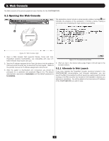
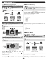
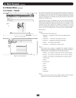
3. Web Console continued 3.2 Web Console Interface B C D 3.3 Device Summary Figure 3-4: Devices The Device Summary displays the current Alarm Status, Model Name, Device Type and user-defined location of a device. Valid Alarm Status values include: • NORMAL • INFORMATION • WARNING • STATUS • CRITICAL • OFFLINE Model Name is detected automatically and is not editable by the user. Valid Device Type values include • UPS • PDU • ENVIROSENSE • AC Location is user-defined. There is no default value for location. 3.4 Status Menu 3.4.1 Status > Overview Figure 3-3: Status Pages The header B contains the menu buttons, which are the main navigational icons of the console. After clicking a menu button, the submenu options for the menu C will appear below the header. Figure 3-5: Status Page This is the default screen of information and will the first screen to be displayed. It is a pictorial representation of the state of the system. The values on this screen are not editable. The Device Summary D is always displayed at the top of the screen, while Note: The graphic symbols used are not intended to be a representation the bottom portion of the screen changes as different options are chosen. of the actual equipment connected. 5
-
 1
1 -
 2
2 -
 3
3 -
 4
4 -
 5
5 -
 6
6 -
 7
7 -
 8
8 -
 9
9 -
 10
10 -
 11
11 -
12
-
13
-
14
-
15
-
16
-
17
-
18
-
19
-
20
-
21
-
22
-
23
-
24
-
25
-
26
-
27
-
28
-
29
-
30
-
31
-
32
-
33
-
34
-
35
-
36
-
37
-
38
-
39
-
40
-
41
-
42
-
43
-
44
-
45
-
46
-
47
-
48
-
49
-
50
-
51
-
52
-
53
-
54
-
55
-
56
-
57
-
58
-
59
-
60
-
61
-
62
-
63
-
64
-
65
-
66
-
67
-
68
-
69
-
70
-
71
-
72
-
73
-
74
-
75
-
76
-
77
-
78
-
79
-
80
-
81
-
82
-
83
-
84
-
85
-
86
-
87
-
88
-
89
-
90
-
91
-
92
-
93
-
94
-
95
-
96
-
97
-
98
-
99
-
100
 |
 |
