Tripp Lite PDU3VSR6L2130 Owner's Manual for SNMPWEBCARD 9332CE - Page 8
Device Menu
 |
View all Tripp Lite PDU3VSR6L2130 manuals
Add to My Manuals
Save this manual to your list of manuals |
Page 8 highlights
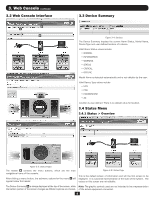
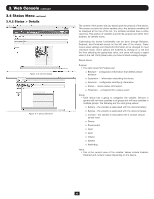
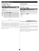
3. Web Console continued 3.5 Device Menu continued 3.5.2 Device > Loads 3.5.3 Device > Load Groups Figure 3-10: Loads Figure 3-11: Load Groups The Loads menu option will only appear if the device supports loads. The description field is an editable value. In order to save any changes made on this page, you must click the [Save] button at the bottom of the page. You can control the outlets of the managed device by selecting the load and then clicking the appropriate [On], [Off] or [Cycle] button. The load of connected equipment is displayed in amps, allowing you to see whether additional equipment can be added safely. (Load fluctuates with the power demands of connected equipment. It is prudent to limit the load to approximately 80% of maximum capacity in order to accommodate higher startup power demands and other increased power needs.) If your device has controllable load banks, additional buttons allow you to control each load bank. (Each load bank consists of one or more outlets.) You can use the "Description" field to label the banks for easy reference. The main control buttons affect all outlets at once. Note: If the control buttons remain grayed out when a load is selected, this condition indicates the outlet is non-controllable. The Load Groups menu option will only appear if the device has two (2) or more controllable loads. To create a load group click the [+] button on the bottom of the screen to add a group row to the table. Then, enter a name and description and click on the Loads cell to expose available loads that can be added to a group. Click on the select loads and then click the [Save] button on the bottom of the screen The description is an editable field. Once changes are made to any, or all, descriptions, click the [Save] button to save the changes. To delete a load group, click on the load group row to delete, click the [-] button and confirm the delete. 8
-
 1
1 -
2
-
 3
3 -
 4
4 -
 5
5 -
 6
6 -
 7
7 -
 8
8 -
 9
9 -
 10
10 -
 11
11 -
 12
12 -
 13
13 -
14
-
15
-
16
-
17
-
18
-
19
-
20
-
21
-
22
-
23
-
24
-
25
-
26
-
27
-
28
-
29
-
30
-
31
-
32
-
33
-
34
-
35
-
36
-
37
-
38
-
39
-
40
-
41
-
42
-
43
-
44
-
45
-
46
-
47
-
48
-
49
-
50
-
51
-
52
-
53
-
54
-
55
-
56
-
57
-
58
-
59
-
60
-
61
-
62
-
63
-
64
-
65
-
66
-
67
-
68
-
69
-
70
-
71
-
72
-
73
-
74
-
75
-
76
-
77
-
78
-
79
-
80
-
81
-
82
-
83
-
84
-
85
-
86
-
87
-
88
-
89
-
90
-
91
-
92
-
93
-
94
-
95
-
96
-
97
-
98
-
99
-
100
 |
 |
