ZyXEL NBG6616 User Guide - Page 15
Wall Mounting, Be careful to avoid damaging pipes or cables located inside the wall
 |
View all ZyXEL NBG6616 manuals
Add to My Manuals
Save this manual to your list of manuals |
Page 15 highlights
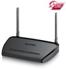
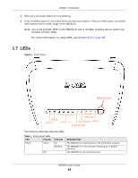
Chapter 1 Introduction Table 1 Front panel LEDs (continued) LED COLOR STATUS WAN Green On Blinking Off LAN 1-4 Green On Blinking Off 2.4G/5G WLAN Green On Blinking WPS Off Green On Blinking USB 1/2 Off Green On Blinking Off DESCRIPTION The NBG6616's WAN connection is ready. The NBG6616 is sending/receiving data through the WAN. The WAN connection is not ready, or has failed. The NBG6616's LAN connection is ready. The NBG6616 is sending/receiving data through the LAN. The LAN connection is not ready, or has failed. The NBG6616 is ready and the 2.4GHz/5GHz wireless LAN is on, but is not sending/receiving data through the wireless LAN. The NBG6616 is sending/receiving data through the wireless LAN. The wireless LAN is not ready or has failed. WPS is enabled. The NBG6616 is negotiating a WPS connection with a wireless client. WPS is disabled. The NBG6616 has a USB device installed. The NBG6616 is transmitting and/or receiving data from routers through an installed USB device. There is no USB device connected to the NBG6616. 1.8 Wall Mounting You may need screw anchors if mounting on a concrete or brick wall. Table 2 Wall Mounting Information Distance between holes M4 Screws Screw anchors (optional) 13 cm Two Two 1 Select a position free of obstructions on a wall strong enough to hold the weight of the device. 2 Mark two holes on the wall at the appropriate distance apart for the screws. Be careful to avoid damaging pipes or cables located inside the wall when drilling holes for the screws. 3 If using screw anchors, drill two holes for the screw anchors into the wall. Push the anchors into the full depth of the holes, then insert the screws into the anchors. Do not insert the screws all the way in - leave a small gap of about 0.5 cm. If not using screw anchors, use a screwdriver to insert the screws into the wall. Do not insert the screws all the way in - leave a gap of about 0.5 cm. 4 Make sure the screws are fastened well enough to hold the weight of the NBG6616 with the connection cables. NBG6616 User's Guide 15
-
 1
1 -
2
-
3
-
4
-
5
-
6
-
7
-
8
-
9
-
 10
10 -
 11
11 -
 12
12 -
 13
13 -
 14
14 -
 15
15 -
 16
16 -
 17
17 -
 18
18 -
 19
19 -
 20
20 -
21
-
22
-
23
-
24
-
25
-
26
-
27
-
28
-
29
-
30
-
31
-
32
-
33
-
34
-
35
-
36
-
37
-
38
-
39
-
40
-
41
-
42
-
43
-
44
-
45
-
46
-
47
-
48
-
49
-
50
-
51
-
52
-
53
-
54
-
55
-
56
-
57
-
58
-
59
-
60
-
61
-
62
-
63
-
64
-
65
-
66
-
67
-
68
-
69
-
70
-
71
-
72
-
73
-
74
-
75
-
76
-
77
-
78
-
79
-
80
-
81
-
82
-
83
-
84
-
85
-
86
-
87
-
88
-
89
-
90
-
91
-
92
-
93
-
94
-
95
-
96
-
97
-
98
-
99
-
100
-
101
-
102
-
103
-
104
-
105
-
106
-
107
-
108
-
109
-
110
-
111
-
112
-
113
-
114
-
115
-
116
-
117
-
118
-
119
-
120
-
121
-
122
-
123
-
124
-
125
-
126
-
127
-
128
-
129
-
130
-
131
-
132
-
133
-
134
-
135
-
136
-
137
-
138
-
139
-
140
-
141
-
142
-
143
-
144
-
145
-
146
-
147
-
148
-
149
-
150
-
151
-
152
-
153
-
154
-
155
-
156
-
157
-
158
-
159
-
160
-
161
-
162
-
163
-
164
-
165
-
166
-
167
-
168
-
169
-
170
-
171
-
172
-
173
-
174
-
175
-
176
-
177
-
178
-
179
-
180
-
181
-
182
-
183
-
184
-
185
-
186
-
187
-
188
-
189
-
190
-
191
-
192
-
193
-
194
-
195
-
196
-
197
-
198
-
199
-
200
-
201
-
202
-
203
-
204
-
205
-
206
-
207
-
208
-
209
-
210
-
211
-
212
-
213
-
214
-
215
-
216
-
217
-
218
-
219
-
220
-
221
-
222
-
223
-
224
-
225
-
226
-
227
-
228
-
229
-
230
-
231
-
232
-
233
-
234
-
235
-
236
-
237
-
238
-
239
-
240
-
241
 |
 |
