Alpine INA-W910 Owner's Manual (english) - Page 126
Video Input Connector AUX INPUT Yellow, AUX I/O / Camera Input Connector
 |
View all Alpine INA-W910 manuals
Add to My Manuals
Save this manual to your list of manuals |
Page 126 highlights
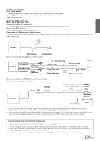
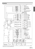
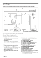
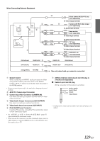
Radio Antenna Receptacle Remote Control Output Lead (White/Brown) Connect this lead to the remote control input lead. This lead outputs the controlling signals from the remote control. Remote Control Input Lead (White/Brown) Connect the external Alpine product to the remote control output lead. Reverse Lead (Orange/White) Use only when a back-up camera is connected. Connect to the plus side of the car's reverse lamp. This lamp illuminates when the transmission is shifted into reverse (R). With this lead properly wired, the video picture automatically switches to the back-up camera whenever the car is put into reverse (R). CAMERA SW Lead (Black) Not used for this unit now. Guide Control Lead (White/Green) Use when an optional External Audio Processor with guide control input terminal is connected. Steering Remote Control Interface Connector (Black) To steering remote control interface box. For details about connections, consult your nearest Alpine dealer. Video Input Connector (AUX INPUT) (Yellow) Input the video. Audio Input Connectors (AUX INPUT) RED is right and WHITE is left input the audio. Video Output Connector (AUX OUTPUT) (Yellow) Output the video. Audio Output Connectors (AUX OUTPUT) RED is right and WHITE is left output the audio. Guide Connector (Black) Output the audio signal of navigation interruption. When connecting an IMPRINT Audio processor (PXA-H100) or an external audio processor with Guide input terminal, connect this lead to the Guide Input terminal with an optional RCA Extension cable. Camera Input RCA Connector (CAMERA IN) Use when connecting an optional camera with RCA video output connector. SiriusXM Tuner connector Connect to a SiriusXM Tuner. Refer to additional installations instructions included with the SiriusXM tuner. Rear Output/Input RCA Connectors It can be used as Rear Output or Input RCA Connectors. Front Output/Input RCA Connectors It can be used as Front Output or Input RCA Connectors. Subwoofer RCA Connectors RED is right and WHITE is left. RCA Extension Cable (sold separately) Direct CAMERA Input Connector Use when the optional direct camera is connected. • When an Alpine rearview camera HCE-C300R is used, please make sure to connect it to this unit via Direct CAMERA Input Connector. iPod (V)/AUX Input Connector Input the iPhone/video compatible iPod audio/video signal or AUX video/audio signal. • Set "AUX2 IN" to "iPod Video" in "Setting the AUX2 Mode" (page 67) when an iPhone or a video compatible iPod is connected. • Set "AUX2 IN" to "AUX" in "Setting the AUX2 Mode" (page 67) when normal AUX video/audio is input. GPS Antenna Receptacle To GPS Antenna. MIC Input Connector To Microphone (supplied). Ai-NET Connector Connect this to the output or input connector of another device (CD Changer, Equalizer, etc.) equipped with Ai-NET. • Be sure to set "Setting the Connected Head Unit (MODEL SETUP)" to "DVD CHG", when the DHA-S690 is connected. USB Connector AUX I/O / Camera Input Connector RCA Output/Input Connector System Switch When connecting an equalizer or divider using Ai-NET feature, place the switch in the EQ/DIV position. When no device is connected, leave the switch in the NORM position. • Be sure to turn the power off to the unit before changing the switch position. Power Supply Connector Digital Output Terminal (Optical) Use when combining fiber optic digital input compatible products. Be sure to use the Optical Digital Cable (KWE-610A) (sold separately) only. Ai-NET Cable (Included with CD Changer) Remote Turn-On Lead (Blue/White) Connect this lead to the remote turn-on lead of your amplifier or signal processor. Power Antenna Lead (Blue) Connect this lead to the +B terminal of your power antenna, if applicable. • This lead should be used only for controlling the vehicle's power antenna. Do not use this lead to turn on an amplifier or a signal processor, etc. Audio Interrupt In Lead (Pink/Black) Not used for this unit. Parking Brake Lead (Yellow/Blue) Connect this lead to the power supply side of the parking brake switch to transmit the parking brake status signals to the INA-W910. Foot Brake Lead (Yellow/Black) Connect to the vehicle's foot brake lead or brake lamp lead. 126-EN
-
 1
1 -
2
-
3
-
4
-
5
-
6
-
7
-
8
-
9
-
10
-
11
-
12
-
13
-
14
-
15
-
16
-
17
-
18
-
19
-
20
-
21
-
22
-
23
-
24
-
25
-
26
-
27
-
28
-
29
-
30
-
31
-
32
-
33
-
34
-
35
-
36
-
37
-
38
-
39
-
40
-
41
-
42
-
43
-
44
-
45
-
46
-
47
-
48
-
49
-
50
-
51
-
52
-
53
-
54
-
55
-
56
-
57
-
58
-
59
-
60
-
61
-
62
-
63
-
64
-
65
-
66
-
67
-
68
-
69
-
70
-
71
-
72
-
73
-
74
-
75
-
76
-
77
-
78
-
79
-
80
-
81
-
82
-
83
-
84
-
85
-
86
-
87
-
88
-
89
-
90
-
91
-
92
-
93
-
94
-
95
-
96
-
97
-
98
-
99
-
100
-
101
-
102
-
103
-
104
-
105
-
106
-
107
-
108
-
109
-
110
-
111
-
112
-
113
-
114
-
115
-
116
-
117
-
118
-
119
-
120
-
 121
121 -
 122
122 -
 123
123 -
 124
124 -
 125
125 -
 126
126 -
 127
127 -
 128
128 -
 129
129 -
 130
130 -
 131
131
 |
 |