Cisco SPA1001 Administration Guide - Page 31
PAP2T - firmware upgrade
 |
View all Cisco SPA1001 manuals
Add to My Manuals
Save this manual to your list of manuals |
Page 31 highlights
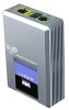
Chapter 2 Getting Started Linksys Analog Telephone Adapters (ATAs) Table 1-5 AG310 Front Panel LED Power Ethernet 1-4 Voice Status Phone Line DSL Internet Function Steady green indicates power on and Internet connection. Flashing indicates not connected to the Internet, booting or firmware upgrade. Steady green indicates an active connection to the network. Flashing indicates traffic. Steady green indicates that a voice call is currently in progress. Steady green indicates active or registered connection to the ITSP through the Phone port. Flashing indicates device is in use or off hook. Steady green when a telephone or fax machine has an active connection to traditional phone service through the Line port. Steady green indicates that the DSL connection is active. Steady green indicates active connection. Flashing indicates traffic. PAP2T Table 1-6 AG310 Back Panel Port DSL Line Phone Ethernet 1-4 Power Function Connect to the telephone wall jack providing DSL service using a RJ-11 cable. Connect to a standard telephone wall jack with an RJ-11cable. Connect to an analog telephone or fax machine with an RJ-11 cable. Connect to network devices, such as a PC or a switch, using an Ethernet cable. Connect to the power supply. The PAP2T provides two FXS ports (see Figure 1-5). Document Version 3.1 Linksys ATA Administrator Guide 2-3
-
 1
1 -
2
-
3
-
4
-
5
-
6
-
7
-
8
-
9
-
10
-
11
-
12
-
13
-
14
-
15
-
16
-
17
-
18
-
19
-
20
-
21
-
22
-
23
-
24
-
25
-
 26
26 -
 27
27 -
 28
28 -
 29
29 -
 30
30 -
 31
31 -
 32
32 -
 33
33 -
 34
34 -
 35
35 -
 36
36 -
37
-
38
-
39
-
40
-
41
-
42
-
43
-
44
-
45
-
46
-
47
-
48
-
49
-
50
-
51
-
52
-
53
-
54
-
55
-
56
-
57
-
58
-
59
-
60
-
61
-
62
-
63
-
64
-
65
-
66
-
67
-
68
-
69
-
70
-
71
-
72
-
73
-
74
-
75
-
76
-
77
-
78
-
79
-
80
-
81
-
82
-
83
-
84
-
85
-
86
-
87
-
88
-
89
-
90
-
91
-
92
-
93
-
94
-
95
-
96
-
97
-
98
-
99
-
100
-
101
-
102
-
103
-
104
-
105
-
106
-
107
-
108
-
109
-
110
-
111
-
112
-
113
-
114
-
115
-
116
-
117
-
118
-
119
-
120
-
121
-
122
-
123
-
124
-
125
-
126
-
127
-
128
-
129
-
130
-
131
-
132
-
133
-
134
-
135
-
136
-
137
-
138
-
139
-
140
-
141
-
142
-
143
-
144
-
145
-
146
-
147
-
148
-
149
-
150
-
151
-
152
-
153
-
154
-
155
-
156
-
157
-
158
-
159
-
160
-
161
-
162
-
163
-
164
-
165
-
166
-
167
-
168
-
169
-
170
-
171
-
172
-
173
-
174
-
175
-
176
-
177
-
178
-
179
-
180
-
181
-
182
-
183
-
184
-
185
-
186
 |
 |
