Cisco SPA1001 Administration Guide - Page 40
WRTP54G, Table 1-20, WRTP54G Front Panel, Table 1-21, WRTP54G Back Panel
 |
View all Cisco SPA1001 manuals
Add to My Manuals
Save this manual to your list of manuals |
Page 40 highlights
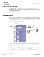
Linksys Analog Telephone Adapters (ATAs) Figure 1-12 WRTP54G Chapter 2 Getting Started The following tables describe the LEDS on the front panel and the ports on the back panel of the device Table 1-20 WRTP54G Front Panel LED Ethernet 1-4 Wireless Phone 1/2 Internet Function Steady green indicates an active connection to the network. Flashing indicates traffic. Steady green indicates an active connection to the network. Flashing indicates traffic. Steady green when telephone or fax machine has an active or registered connection to the ITSP through the Phone port. Flashing indicates phone is in use or off hook. Steady green indicates active connection. Flashing indicates traffic. Table 1-21 WRTP54G Back Panel Port Internet Phone 1/2 Ethernet 1-4 Power Function Connect to the broadband (cable/DSL) modem using an Ethernet cable. Connect to an analog telephone or fax machine using an RJ-11 cable. Connect to local IP devices, such as PCs, using an Ethernet cable. Connect to the 12-volt power supply. 2-12 Linksys ATA Administrator Guide Document Version 3.1
-
 1
1 -
2
-
3
-
4
-
5
-
6
-
7
-
8
-
9
-
10
-
11
-
12
-
13
-
14
-
15
-
16
-
17
-
18
-
19
-
20
-
21
-
22
-
23
-
24
-
25
-
26
-
27
-
28
-
29
-
30
-
31
-
32
-
33
-
34
-
 35
35 -
 36
36 -
 37
37 -
 38
38 -
 39
39 -
 40
40 -
 41
41 -
 42
42 -
 43
43 -
 44
44 -
 45
45 -
46
-
47
-
48
-
49
-
50
-
51
-
52
-
53
-
54
-
55
-
56
-
57
-
58
-
59
-
60
-
61
-
62
-
63
-
64
-
65
-
66
-
67
-
68
-
69
-
70
-
71
-
72
-
73
-
74
-
75
-
76
-
77
-
78
-
79
-
80
-
81
-
82
-
83
-
84
-
85
-
86
-
87
-
88
-
89
-
90
-
91
-
92
-
93
-
94
-
95
-
96
-
97
-
98
-
99
-
100
-
101
-
102
-
103
-
104
-
105
-
106
-
107
-
108
-
109
-
110
-
111
-
112
-
113
-
114
-
115
-
116
-
117
-
118
-
119
-
120
-
121
-
122
-
123
-
124
-
125
-
126
-
127
-
128
-
129
-
130
-
131
-
132
-
133
-
134
-
135
-
136
-
137
-
138
-
139
-
140
-
141
-
142
-
143
-
144
-
145
-
146
-
147
-
148
-
149
-
150
-
151
-
152
-
153
-
154
-
155
-
156
-
157
-
158
-
159
-
160
-
161
-
162
-
163
-
164
-
165
-
166
-
167
-
168
-
169
-
170
-
171
-
172
-
173
-
174
-
175
-
176
-
177
-
178
-
179
-
180
-
181
-
182
-
183
-
184
-
185
-
186
 |
 |
