Cisco SPA1001 Administration Guide - Page 44
Connecting the SPA8000
 |
View all Cisco SPA1001 manuals
Add to My Manuals
Save this manual to your list of manuals |
Page 44 highlights
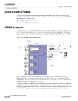
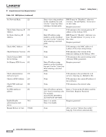
Connecting the SPA8000 Chapter 2 Getting Started Connecting the SPA8000 The SPA8000 provides up to eight analog telephone connections, and is designed to function as a network endpoint. This section describes the architecture and connectivy requirements of the SPA8000 and includes the following topics: • SPA8000 Architecture, page 2-16 • Connectivity Requirements, page 2-17 SPA8000 Architecture As shown in Figure 1-14, the SPA8000 consists of four hardware modules: one primary (Module 1) and three secondary modules (Modules 2, 3, and 4). Each module provides two FXS ports. The primary module supports Line 1 and Line 2, while the three secondary modules support Line 3-4, 5-6, and 7-8. Figure 1-14 SPA8000 Internal Configuration Administrative IVR (Line 1 or Line 2) 8 FXS (RJ11/RJ-21 ) ports SPA8000 Module 1 (primary) 192.168.1.101 Line 1 NAT/PAT Internal DHCP Line 2 server 192.168.0.1 Line 3 Line 4 Module 2 (secondary) 192.168.0.2 Ethernet port IP Router (with hairpinning) or Broadband modem ISP 192.168.1.100 209.165.202.129 AUX port Administration web server 192.168.0.5 Internet ITSP Line 5 Line 6 Module 3 (secondary) 192.168.0.3 Secondary Module 2 Line 7 Line 8 Module 4 (secondary) 192.168.0.4 The four modules are interconnected through an internal IP network, configured automatically as a single subnet, which by default is assigned the network address 192.168.0.0 with a subnet mask of 255.255.255.0. If a network conflict is detected from the device connected on the AUX port, the internal network is automatically changed to 192.168.1.0. The primary module is responsible for the management functions of the entire SPA8000, in addition to handling calls on Line 1 and Line 2. These management functions include remote provisioning, firmware upgrades, the administration web server, IVR functions, and SIP NOTIFY control messages (over Line 1 or 2). The IVR functions are accessed by connecting an analog telephone to Line 1 or Line 2. 2-16 Linksys ATA Administrator Guide Document Version 3.1
-
 1
1 -
2
-
3
-
4
-
5
-
6
-
7
-
8
-
9
-
10
-
11
-
12
-
13
-
14
-
15
-
16
-
17
-
18
-
19
-
20
-
21
-
22
-
23
-
24
-
25
-
26
-
27
-
28
-
29
-
30
-
31
-
32
-
33
-
34
-
35
-
36
-
37
-
38
-
 39
39 -
 40
40 -
 41
41 -
 42
42 -
 43
43 -
 44
44 -
 45
45 -
 46
46 -
 47
47 -
 48
48 -
 49
49 -
50
-
51
-
52
-
53
-
54
-
55
-
56
-
57
-
58
-
59
-
60
-
61
-
62
-
63
-
64
-
65
-
66
-
67
-
68
-
69
-
70
-
71
-
72
-
73
-
74
-
75
-
76
-
77
-
78
-
79
-
80
-
81
-
82
-
83
-
84
-
85
-
86
-
87
-
88
-
89
-
90
-
91
-
92
-
93
-
94
-
95
-
96
-
97
-
98
-
99
-
100
-
101
-
102
-
103
-
104
-
105
-
106
-
107
-
108
-
109
-
110
-
111
-
112
-
113
-
114
-
115
-
116
-
117
-
118
-
119
-
120
-
121
-
122
-
123
-
124
-
125
-
126
-
127
-
128
-
129
-
130
-
131
-
132
-
133
-
134
-
135
-
136
-
137
-
138
-
139
-
140
-
141
-
142
-
143
-
144
-
145
-
146
-
147
-
148
-
149
-
150
-
151
-
152
-
153
-
154
-
155
-
156
-
157
-
158
-
159
-
160
-
161
-
162
-
163
-
164
-
165
-
166
-
167
-
168
-
169
-
170
-
171
-
172
-
173
-
174
-
175
-
176
-
177
-
178
-
179
-
180
-
181
-
182
-
183
-
184
-
185
-
186
 |
 |
