Dell Latitude D610 User Guide - Page 6
Back View - usb 2 0
 |
View all Dell Latitude D610 manuals
Add to My Manuals
Save this manual to your list of manuals |
Page 6 highlights
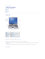
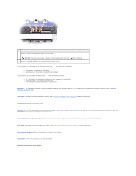
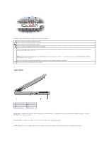
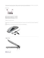
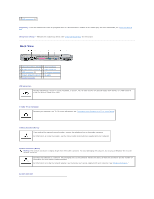
3 USB connectors (2) module bay - You can install devices such as an optical drive or a Dell TravelLite™ module in the module bay. For more information, see "Using the Module Bay." device latch release - Releases the module bay device. See "Using the Module Bay" for instructions. Back View 1 network connector (RJ-45) 6 serial connector 2 S-video TV-out connector 7 video connector 3 USB connectors (2) 8 AC adapter connector 4 modem connector (RJ-11) 9 air vents 5 parallel connector USB connectors Connect USB devices, such as a mouse, keyboard, or printer. You can also connect the optional floppy drive directly to a USB connector using the optional floppy drive cable. S-video TV-out connector Connects your computer to a TV. For more information, see "Connecting Your Computer to a TV or Audio Device." modem connector (RJ-11) If you ordered the optional internal modem, connect the telephone line to the modem connector. For information on using the modem, see the online modem documentation supplied with your computer. network connector (RJ-45) NOTICE: The network connector is slightly larger than the modem connector. To avoid damaging the computer, do not plug a telephone line into the network connector. Connects the computer to a network. The two lights next to the connector indicate the status of both the connection and the transfer of information for wired network communications. For information on using the network adapter, see the device user's guide supplied with your computer. See "Finding Information." parallel connector
-
 1
1 -
 2
2 -
 3
3 -
 4
4 -
 5
5 -
 6
6 -
 7
7 -
 8
8 -
 9
9 -
 10
10 -
 11
11 -
 12
12 -
13
-
14
-
15
-
16
-
17
-
18
-
19
-
20
-
21
-
22
-
23
-
24
-
25
-
26
-
27
-
28
-
29
-
30
-
31
-
32
-
33
-
34
-
35
-
36
-
37
-
38
-
39
-
40
-
41
-
42
-
43
-
44
-
45
-
46
-
47
-
48
-
49
-
50
-
51
-
52
-
53
-
54
-
55
-
56
-
57
-
58
-
59
-
60
-
61
-
62
-
63
-
64
-
65
-
66
-
67
-
68
-
69
-
70
-
71
-
72
-
73
-
74
-
75
-
76
-
77
-
78
-
79
-
80
-
81
-
82
-
83
-
84
-
85
-
86
-
87
-
88
-
89
-
90
-
91
-
92
-
93
-
94
-
95
-
96
-
97
-
98
-
99
-
100
-
101
-
102
-
103
-
104
-
105
-
106
-
107
-
108
-
109
-
110
-
111
-
112
-
113
-
114
-
115
 |
 |
