HP 2600n Service Manual - Page 165
Order replacement parts from the following Web site, Overview, Table 7-1 - black toner cartridge
 |
UPC - 829160809366
View all HP 2600n manuals
Add to My Manuals
Save this manual to your list of manuals |
Page 165 highlights
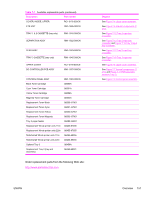
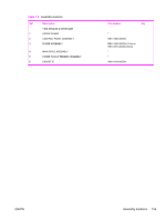
Table 7-1 Available replaceable parts (continued) Description Part number COVER, INSIDE, UPPER RC1-5178-000CN ETB UNIT RM1-1885-000CN TRAY 1 & 2 CASSETTE (tray only) RM1-1916-000CN SEPARATION ASSY RM1-1922-000CN FEED ASSY TRAY 3 CASSETTE (tray only) UPPER COVER DC CONTROLLER PCB ASSY RM1-1923-000CN RM1-1945-000CN RC1-5176-000CN RM1-1975-000CN CONTROL PANEL ASSY Black Toner Cartridge Cyan Toner Cartridge Yellow Toner Cartridge Magenta Toner Cartridge Replacement-Toner-Black Replacement-Toner-Cyan Replacement-Toner-Yellow Replacement-Toner-Magenta Tray 3 paper feeder Replacement Whole printer units 110v Replacement Whole printer units 220v Refurbished Whole printer units 110v Refurbished Whole printer units 220v Optional Tray 3 Replacement Tray 3 (tray and assembly) RM1-1983-000CN Q6000A Q6001A Q6002A Q6003A Q6000-67901 Q6001-67901 Q6002-67901 Q6003-67901 Q6459-69001 Q6455-67056 Q6455-67055 Q6455-69056 Q6455-69055 Q6459A Q6459-69001 Order replacement parts from the following Web site: http://www.partsdirect.hp.com Diagram See Figure 7-4 Upper cover assembly. See Figure 7-6 Internal components (2 of 3). See Figure 7-12 Tray 2 input tray (cassette). See Figure 7-12 Tray 2 input tray (cassette) and Figure 7-16 Tray 3 input tray (cassette). See Figure 7-12 Tray 2 input tray (cassette). See Figure 7-16 Tray 3 input tray (cassette). See Figure 7-4 Upper cover assembly. See Figure 7-7 Internal components (3 of 3) and Figure 7-11 PCB assembly location (Tray 2). See Figure 7-8 Control panel assembly. ENWW Overview 151
-
 1
1 -
2
-
3
-
4
-
5
-
6
-
7
-
8
-
9
-
10
-
11
-
12
-
13
-
14
-
15
-
16
-
17
-
18
-
19
-
20
-
21
-
22
-
23
-
24
-
25
-
26
-
27
-
28
-
29
-
30
-
31
-
32
-
33
-
34
-
35
-
36
-
37
-
38
-
39
-
40
-
41
-
42
-
43
-
44
-
45
-
46
-
47
-
48
-
49
-
50
-
51
-
52
-
53
-
54
-
55
-
56
-
57
-
58
-
59
-
60
-
61
-
62
-
63
-
64
-
65
-
66
-
67
-
68
-
69
-
70
-
71
-
72
-
73
-
74
-
75
-
76
-
77
-
78
-
79
-
80
-
81
-
82
-
83
-
84
-
85
-
86
-
87
-
88
-
89
-
90
-
91
-
92
-
93
-
94
-
95
-
96
-
97
-
98
-
99
-
100
-
101
-
102
-
103
-
104
-
105
-
106
-
107
-
108
-
109
-
110
-
111
-
112
-
113
-
114
-
115
-
116
-
117
-
118
-
119
-
120
-
121
-
122
-
123
-
124
-
125
-
126
-
127
-
128
-
129
-
130
-
131
-
132
-
133
-
134
-
135
-
136
-
137
-
138
-
139
-
140
-
141
-
142
-
143
-
144
-
145
-
146
-
147
-
148
-
149
-
150
-
151
-
152
-
153
-
154
-
155
-
156
-
157
-
158
-
159
-
 160
160 -
 161
161 -
 162
162 -
 163
163 -
 164
164 -
 165
165 -
 166
166 -
 167
167 -
 168
168 -
 169
169 -
 170
170 -
171
-
172
-
173
-
174
-
175
-
176
-
177
-
178
-
179
-
180
-
181
-
182
-
183
-
184
-
185
-
186
-
187
-
188
-
189
-
190
-
191
-
192
-
193
-
194
-
195
-
196
-
197
-
198
-
199
-
200
-
201
-
202
-
203
-
204
-
205
-
206
-
207
-
208
-
209
-
210
-
211
-
212
-
213
-
214
-
215
-
216
-
217
-
218
-
219
-
220
-
221
-
222
-
223
-
224
-
225
-
226
-
227
-
228
-
229
-
230
-
231
-
232
-
233
-
234
-
235
-
236
-
237
-
238
-
239
-
240
-
241
-
242
-
243
-
244
-
245
-
246
-
247
-
248
-
249
-
250
-
251
-
252
-
253
-
254
-
255
-
256
-
257
-
258
-
259
-
260
-
261
-
262
-
263
-
264
-
265
-
266
-
267
-
268
-
269
-
270
-
271
-
272
-
273
-
274
-
275
-
276
-
277
-
278
-
279
-
280
-
281
-
282
-
283
-
284
-
285
-
286
-
287
-
288
-
289
-
290
 |
 |
