HP 2600n Service Manual - Page 69
Solenoid, motor, and fan locations, Printed circuit assembly locations,
 |
UPC - 829160809366
View all HP 2600n manuals
Add to My Manuals
Save this manual to your list of manuals |
Page 69 highlights
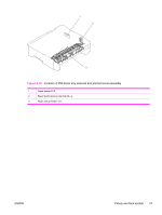
Solenoid, motor, and fan locations The following illustration shows the locations of the solenoids, motor, and fan. Figure 4-14 Location of solenoids, motors, and fans 1 Pickup solenoid (SL1) 2 Magenta, cyan, and yellow developing cylinder drive solenoid (SL2) 3 Black developing cylinder drive solenoid (SL3) 4 Main motor (M1) 5 Fusing/delivery motor (M2) 6 Pickup motor (M3) 7 Fan (FM1) Printed circuit assembly locations The following illustration shows the locations of the printed circuit assemblies. Location of the printed circuit assemblies and list of parts are also identified in Figure 7-11 PCB assembly location (Tray 2). ENWW Pickup and feed system 55
-
 1
1 -
2
-
3
-
4
-
5
-
6
-
7
-
8
-
9
-
10
-
11
-
12
-
13
-
14
-
15
-
16
-
17
-
18
-
19
-
20
-
21
-
22
-
23
-
24
-
25
-
26
-
27
-
28
-
29
-
30
-
31
-
32
-
33
-
34
-
35
-
36
-
37
-
38
-
39
-
40
-
41
-
42
-
43
-
44
-
45
-
46
-
47
-
48
-
49
-
50
-
51
-
52
-
53
-
54
-
55
-
56
-
57
-
58
-
59
-
60
-
61
-
62
-
63
-
 64
64 -
 65
65 -
 66
66 -
 67
67 -
 68
68 -
 69
69 -
 70
70 -
 71
71 -
 72
72 -
 73
73 -
 74
74 -
75
-
76
-
77
-
78
-
79
-
80
-
81
-
82
-
83
-
84
-
85
-
86
-
87
-
88
-
89
-
90
-
91
-
92
-
93
-
94
-
95
-
96
-
97
-
98
-
99
-
100
-
101
-
102
-
103
-
104
-
105
-
106
-
107
-
108
-
109
-
110
-
111
-
112
-
113
-
114
-
115
-
116
-
117
-
118
-
119
-
120
-
121
-
122
-
123
-
124
-
125
-
126
-
127
-
128
-
129
-
130
-
131
-
132
-
133
-
134
-
135
-
136
-
137
-
138
-
139
-
140
-
141
-
142
-
143
-
144
-
145
-
146
-
147
-
148
-
149
-
150
-
151
-
152
-
153
-
154
-
155
-
156
-
157
-
158
-
159
-
160
-
161
-
162
-
163
-
164
-
165
-
166
-
167
-
168
-
169
-
170
-
171
-
172
-
173
-
174
-
175
-
176
-
177
-
178
-
179
-
180
-
181
-
182
-
183
-
184
-
185
-
186
-
187
-
188
-
189
-
190
-
191
-
192
-
193
-
194
-
195
-
196
-
197
-
198
-
199
-
200
-
201
-
202
-
203
-
204
-
205
-
206
-
207
-
208
-
209
-
210
-
211
-
212
-
213
-
214
-
215
-
216
-
217
-
218
-
219
-
220
-
221
-
222
-
223
-
224
-
225
-
226
-
227
-
228
-
229
-
230
-
231
-
232
-
233
-
234
-
235
-
236
-
237
-
238
-
239
-
240
-
241
-
242
-
243
-
244
-
245
-
246
-
247
-
248
-
249
-
250
-
251
-
252
-
253
-
254
-
255
-
256
-
257
-
258
-
259
-
260
-
261
-
262
-
263
-
264
-
265
-
266
-
267
-
268
-
269
-
270
-
271
-
272
-
273
-
274
-
275
-
276
-
277
-
278
-
279
-
280
-
281
-
282
-
283
-
284
-
285
-
286
-
287
-
288
-
289
-
290
 |
 |
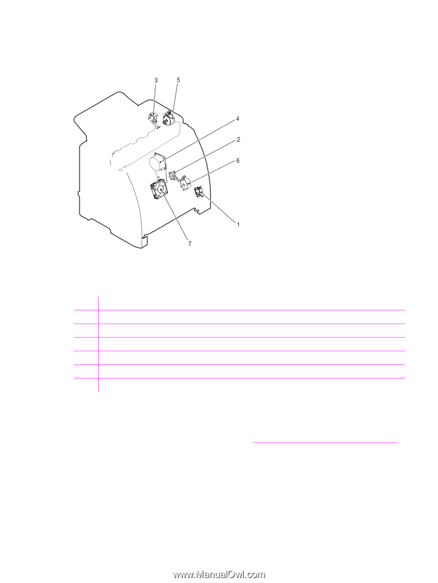
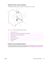
Solenoid, motor, and fan locations
The following illustration shows the locations of the solenoids, motor, and fan.
Figure 4-14
Location of solenoids, motors, and fans
1
Pickup solenoid (SL1)
2
Magenta, cyan, and yellow developing cylinder drive solenoid (SL2)
3
Black developing cylinder drive solenoid (SL3)
4
Main motor (M1)
5
Fusing/delivery motor (M2)
6
Pickup motor (M3)
7
Fan (FM1)
Printed circuit assembly locations
The following illustration shows the locations of the printed circuit assemblies. Location of the printed
circuit assemblies and list of parts are also identified in
Figure
7-11
PCB
assembly
location
(Tray 2)
.
ENWW
Pickup and feed system
55