HP 2600n Service Manual - Page 250
Screw, W/washer, M3x8, Plate, Control Panel Retaining
 |
UPC - 829160809366
View all HP 2600n manuals
Add to My Manuals
Save this manual to your list of manuals |
Page 250 highlights
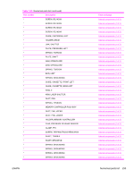
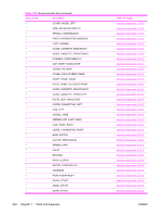
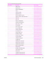
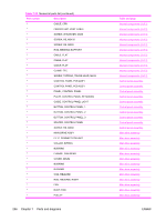
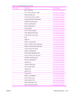
Table 7-23 Numerical parts list (continued) Part number Description * CABLE, CPR * FEEDER UNIT JOINT CABLE * SCREW, W/WASHER, M3X8 * SCREW, RS, M3X10 * SCREW, RS, M3X8 * ROD, BEARING SUPPORT * CABLE, FLAT * CABLE, FLAT * CABLE, FLAT * CLAMP, FFC * SCREW, TAPPING, TRUSS HEAD, M4X8 * CONTROL PANEL PCB ASS'Y * CONTROL PANEL PCB ASS'Y * PANEL, CONTROL PANEL * PLATE, CONTROL PANEL RETAINING * GUIDE, CONTROL PANEL LIGHT * BUTTON, CONTROL PANEL, 1 * BUTTON, CONTROL PANEL, 2 * BUTTON, CONTROL PANEL, 3 * SPACER, CONTROL PANEL * SCREW, RS, M3X8 * MAIN DRIVE ASS'Y * F.F.C. CONNECT PCB UNIT * COLLAR, SPRING * BUSHING * FLANGE, CAM GEAR * COVER, DRUM * BUSHING * BUSHING * CAM, RELEASE * ROD, RELEASE, RIGHT * FAN * DUCT, FAN * PULLEY 236 Chapter 7 Parts and diagrams Table and page Internal components (3 of 3) Internal components (3 of 3) Internal components (3 of 3) Internal components (3 of 3) Internal components (3 of 3) Internal components (3 of 3) Internal components (3 of 3) Internal components (3 of 3) Internal components (3 of 3) Internal components (3 of 3) Internal components (3 of 3) Control panel assembly Control panel assembly Control panel assembly Control panel assembly Control panel assembly Control panel assembly Control panel assembly Control panel assembly Control panel assembly Control panel assembly Main drive assembly Main drive assembly Main drive assembly Main drive assembly Main drive assembly Main drive assembly Main drive assembly Main drive assembly Main drive assembly Main drive assembly Main drive assembly Main drive assembly Main drive assembly ENWW
-
 1
1 -
2
-
3
-
4
-
5
-
6
-
7
-
8
-
9
-
10
-
11
-
12
-
13
-
14
-
15
-
16
-
17
-
18
-
19
-
20
-
21
-
22
-
23
-
24
-
25
-
26
-
27
-
28
-
29
-
30
-
31
-
32
-
33
-
34
-
35
-
36
-
37
-
38
-
39
-
40
-
41
-
42
-
43
-
44
-
45
-
46
-
47
-
48
-
49
-
50
-
51
-
52
-
53
-
54
-
55
-
56
-
57
-
58
-
59
-
60
-
61
-
62
-
63
-
64
-
65
-
66
-
67
-
68
-
69
-
70
-
71
-
72
-
73
-
74
-
75
-
76
-
77
-
78
-
79
-
80
-
81
-
82
-
83
-
84
-
85
-
86
-
87
-
88
-
89
-
90
-
91
-
92
-
93
-
94
-
95
-
96
-
97
-
98
-
99
-
100
-
101
-
102
-
103
-
104
-
105
-
106
-
107
-
108
-
109
-
110
-
111
-
112
-
113
-
114
-
115
-
116
-
117
-
118
-
119
-
120
-
121
-
122
-
123
-
124
-
125
-
126
-
127
-
128
-
129
-
130
-
131
-
132
-
133
-
134
-
135
-
136
-
137
-
138
-
139
-
140
-
141
-
142
-
143
-
144
-
145
-
146
-
147
-
148
-
149
-
150
-
151
-
152
-
153
-
154
-
155
-
156
-
157
-
158
-
159
-
160
-
161
-
162
-
163
-
164
-
165
-
166
-
167
-
168
-
169
-
170
-
171
-
172
-
173
-
174
-
175
-
176
-
177
-
178
-
179
-
180
-
181
-
182
-
183
-
184
-
185
-
186
-
187
-
188
-
189
-
190
-
191
-
192
-
193
-
194
-
195
-
196
-
197
-
198
-
199
-
200
-
201
-
202
-
203
-
204
-
205
-
206
-
207
-
208
-
209
-
210
-
211
-
212
-
213
-
214
-
215
-
216
-
217
-
218
-
219
-
220
-
221
-
222
-
223
-
224
-
225
-
226
-
227
-
228
-
229
-
230
-
231
-
232
-
233
-
234
-
235
-
236
-
237
-
238
-
239
-
240
-
241
-
242
-
243
-
244
-
 245
245 -
 246
246 -
 247
247 -
 248
248 -
 249
249 -
 250
250 -
 251
251 -
 252
252 -
 253
253 -
 254
254 -
 255
255 -
256
-
257
-
258
-
259
-
260
-
261
-
262
-
263
-
264
-
265
-
266
-
267
-
268
-
269
-
270
-
271
-
272
-
273
-
274
-
275
-
276
-
277
-
278
-
279
-
280
-
281
-
282
-
283
-
284
-
285
-
286
-
287
-
288
-
289
-
290
 |
 |
