HP Visualize J5000 hp Visualize J5000, J7000 workstations service handbook (a4 - Page 107
Notice
 |
View all HP Visualize J5000 manuals
Add to My Manuals
Save this manual to your list of manuals |
Page 107 highlights
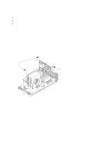
CPU Processor Module Remove four screws and pull shroud straight up. Disconnect fan cable from system board. Figure 5-20. Removing the CPU Processor Module (J280) 4. To remove a processor module, grasp the board and pull straight up. NOTICE: If you have only one processor, it must be installed in CPU slot 0. 5. To replace a module or add a second module, insert the board into the guides and press firmly and evenly into place to ensure the board is properly seated. Make sure that the protective dust cover is removed from the processor module connector on the motherboard and the replacement processor module. See Figure 5-21 or Figure 5-22. 6. Replace the CPU shroud over the processor and replace the six screws attaching the CPU shroud to the system board. 7. Reconnect the fan cable to the system board. CAUTION: Failure to reconnect the fan cable to the system board WILL cause the processor modules to overheat. This can badly damage the processor modules. Field Replaceable Units 5-25
-
 1
1 -
2
-
3
-
4
-
5
-
6
-
7
-
8
-
9
-
10
-
11
-
12
-
13
-
14
-
15
-
16
-
17
-
18
-
19
-
20
-
21
-
22
-
23
-
24
-
25
-
26
-
27
-
28
-
29
-
30
-
31
-
32
-
33
-
34
-
35
-
36
-
37
-
38
-
39
-
40
-
41
-
42
-
43
-
44
-
45
-
46
-
47
-
48
-
49
-
50
-
51
-
52
-
53
-
54
-
55
-
56
-
57
-
58
-
59
-
60
-
61
-
62
-
63
-
64
-
65
-
66
-
67
-
68
-
69
-
70
-
71
-
72
-
73
-
74
-
75
-
76
-
77
-
78
-
79
-
80
-
81
-
82
-
83
-
84
-
85
-
86
-
87
-
88
-
89
-
90
-
91
-
92
-
93
-
94
-
95
-
96
-
97
-
98
-
99
-
100
-
101
-
 102
102 -
 103
103 -
 104
104 -
 105
105 -
 106
106 -
 107
107 -
 108
108 -
 109
109 -
 110
110 -
 111
111 -
 112
112 -
113
-
114
-
115
-
116
-
117
-
118
-
119
-
120
-
121
-
122
-
123
-
124
-
125
-
126
-
127
-
128
-
129
-
130
-
131
-
132
-
133
-
134
-
135
-
136
-
137
-
138
-
139
-
140
-
141
-
142
-
143
-
144
-
145
-
146
-
147
-
148
-
149
-
150
-
151
-
152
-
153
-
154
-
155
-
156
-
157
-
158
-
159
-
160
-
161
-
162
-
163
-
164
-
165
-
166
-
167
-
168
-
169
-
170
-
171
-
172
 |
 |
