HP Visualize J5000 hp Visualize J5000, J7000 workstations service handbook (a4 - Page 110
DIP Switch Settings Reference Only
 |
View all HP Visualize J5000 manuals
Add to My Manuals
Save this manual to your list of manuals |
Page 110 highlights
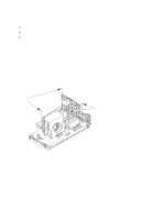
DIP Switch Settings (Reference Only) Before placing the CPU assembly back in the sytem, ensure that the following DIP switches are set correctly. Use Figure 5-23 to locate these switches. D Switch S2 Sets the SCSI host adapter address (always set to 7). 1 always ON 2 always OFF 3 always OFF 4 always OFF D Switch S3 Controls the configuration modes of the main clock generation circuit. J200/210 J280/282 1 normally OFF normally OFF 2 normally OFF normally ON 3 normally OFF normally ON 4 normally OFF normally ON D Switch S4 See separate functions. 1 normally OFF Oscillator selector. When ON, selects the second UV20 oscillator that's mainly used for lab work or debugging. 2 normally OFF Thermal shutdown override. When ON, prevents the power supply from automatically shutting down the system when the power supply temperature exceeds 45° C. 3 Unused 4 Unused For model J200, make sure that the 50 MHz crystal oscillator, part number 1813-1018, is installed in location UT20. For models J210, make sure that the 60 MHz crystal oscillator, part number 1813-1017, is installed in location UT20. For models J280 and J282, make sure that the 45 MHz crystal oscillator, part number 1813-1167, is installed in location UT20. 5-28 Field Replaceable Units
-
 1
1 -
2
-
3
-
4
-
5
-
6
-
7
-
8
-
9
-
10
-
11
-
12
-
13
-
14
-
15
-
16
-
17
-
18
-
19
-
20
-
21
-
22
-
23
-
24
-
25
-
26
-
27
-
28
-
29
-
30
-
31
-
32
-
33
-
34
-
35
-
36
-
37
-
38
-
39
-
40
-
41
-
42
-
43
-
44
-
45
-
46
-
47
-
48
-
49
-
50
-
51
-
52
-
53
-
54
-
55
-
56
-
57
-
58
-
59
-
60
-
61
-
62
-
63
-
64
-
65
-
66
-
67
-
68
-
69
-
70
-
71
-
72
-
73
-
74
-
75
-
76
-
77
-
78
-
79
-
80
-
81
-
82
-
83
-
84
-
85
-
86
-
87
-
88
-
89
-
90
-
91
-
92
-
93
-
94
-
95
-
96
-
97
-
98
-
99
-
100
-
101
-
102
-
103
-
104
-
 105
105 -
 106
106 -
 107
107 -
 108
108 -
 109
109 -
 110
110 -
 111
111 -
 112
112 -
 113
113 -
 114
114 -
 115
115 -
116
-
117
-
118
-
119
-
120
-
121
-
122
-
123
-
124
-
125
-
126
-
127
-
128
-
129
-
130
-
131
-
132
-
133
-
134
-
135
-
136
-
137
-
138
-
139
-
140
-
141
-
142
-
143
-
144
-
145
-
146
-
147
-
148
-
149
-
150
-
151
-
152
-
153
-
154
-
155
-
156
-
157
-
158
-
159
-
160
-
161
-
162
-
163
-
164
-
165
-
166
-
167
-
168
-
169
-
170
-
171
-
172
 |
 |
