HP Visualize J5000 hp Visualize J5000, J7000 workstations service handbook (a4 - Page 40
Configuration
 |
View all HP Visualize J5000 manuals
Add to My Manuals
Save this manual to your list of manuals |
Page 40 highlights
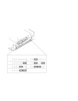
Configuration 3 This chapter provides details about setting up and changing the system configuration. Workstation Configurations Refer to the HP 9000 Series 700 Configuration Guide for a complete list of supported accessories, peripherals, and operating systems for this workstation. FRU Configurations This section provides information for setting up or changing the configuration of the system Field Replaceable Units (FRUs). Internal Storage Configurations Table 3-1 lists the recommended SCSI IDs for internal storage devices. Figures 3-1 and 3-2 show the Fast,Wide Differential SCSI ID settings for the hard disk drives. Figures 3-3 and 3-4 show the Single-Ended SCSI ID settings for the CD-ROM drive and the DDS drive. Figure 3-5 shows the Operation Mode switches for the DDS drive. Figure 3-6 shows the Single-Ended SCSI ID settings for the floppy drive, and Figure 3-7 shows the floppy drive terminator location. NOTICE: There must ALWAYS be a terminator at both ends of a SCSI bus. This means one internal terminator and one external terminator. These SCSI IDs are the recommended IDs for each storage device. If an existing device already uses an ID, select an alternate ID. Table 3-1. Default SCSI IDs Fast-Wide Differential SCSI 1st Hard Disk Drive ID6 2nd Hard Disk Drive ID5 Single-Ended SCSI CD-ROM Drive ID2 DDS Drive ID3 Floppy Drive ID0 Configuration 3-1
-
 1
1 -
2
-
3
-
4
-
5
-
6
-
7
-
8
-
9
-
10
-
11
-
12
-
13
-
14
-
15
-
16
-
17
-
18
-
19
-
20
-
21
-
22
-
23
-
24
-
25
-
26
-
27
-
28
-
29
-
30
-
31
-
32
-
33
-
34
-
 35
35 -
 36
36 -
 37
37 -
 38
38 -
 39
39 -
 40
40 -
 41
41 -
 42
42 -
 43
43 -
 44
44 -
 45
45 -
46
-
47
-
48
-
49
-
50
-
51
-
52
-
53
-
54
-
55
-
56
-
57
-
58
-
59
-
60
-
61
-
62
-
63
-
64
-
65
-
66
-
67
-
68
-
69
-
70
-
71
-
72
-
73
-
74
-
75
-
76
-
77
-
78
-
79
-
80
-
81
-
82
-
83
-
84
-
85
-
86
-
87
-
88
-
89
-
90
-
91
-
92
-
93
-
94
-
95
-
96
-
97
-
98
-
99
-
100
-
101
-
102
-
103
-
104
-
105
-
106
-
107
-
108
-
109
-
110
-
111
-
112
-
113
-
114
-
115
-
116
-
117
-
118
-
119
-
120
-
121
-
122
-
123
-
124
-
125
-
126
-
127
-
128
-
129
-
130
-
131
-
132
-
133
-
134
-
135
-
136
-
137
-
138
-
139
-
140
-
141
-
142
-
143
-
144
-
145
-
146
-
147
-
148
-
149
-
150
-
151
-
152
-
153
-
154
-
155
-
156
-
157
-
158
-
159
-
160
-
161
-
162
-
163
-
164
-
165
-
166
-
167
-
168
-
169
-
170
-
171
-
172
 |
 |
