HP Visualize J5000 hp Visualize J5000, J7000 workstations service handbook (a4 - Page 49
Memory
 |
View all HP Visualize J5000 manuals
Add to My Manuals
Save this manual to your list of manuals |
Page 49 highlights
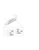
Memory This workstation has 16 memory slots, labeled 0A, 0B through 7A, 7B. Memory can be configured from 32 MB to 256 MB installed in pairs of 16 MB SIMMs, 128 MB to 768 MB (128 MB to 1 GB if you are running HP-UX 10.0), installed in pairs of 64 MB SIMMs, or memory can be cofigured in combinations of pairs of 32 MB and 128 MB SIMM pairs. Memory SIMMs must be installed in pairs of equal size, with 128 MB SIMM pairs installed first, followed by 32 MB SIMM pairs. Figure 3-9 gives the recommended order for installing pairs of SIMMs. 7B Pair 8 7A 5B Pair 6 5A Front of System 6B Pair 7 6A 4B Pair 5 4A J18 3B J17 Pair 4 J16 3A J15 J31 J30 1B J29 Pair 2 J28 1A CPU Modules J26 2B J25 Pair 3 J24 2A J23 J22 J21 0B J20 Pair 1 J19 0A Figure 3-9. Memory Connectors NOTICE: Any combination of memory may be used although, for maximum performance, the use of common-sized memory boards is recommended; either all 32 MB or 128 MB board pairs. Therefore, users who wish to achieve both maximum performance and maximum future capacity are advised to use 128 MB board pairs exclusively. See chapter 5 of this manual for details on installing memory modules. 3-10 Configuration
-
 1
1 -
2
-
3
-
4
-
5
-
6
-
7
-
8
-
9
-
10
-
11
-
12
-
13
-
14
-
15
-
16
-
17
-
18
-
19
-
20
-
21
-
22
-
23
-
24
-
25
-
26
-
27
-
28
-
29
-
30
-
31
-
32
-
33
-
34
-
35
-
36
-
37
-
38
-
39
-
40
-
41
-
42
-
43
-
 44
44 -
 45
45 -
 46
46 -
 47
47 -
 48
48 -
 49
49 -
 50
50 -
 51
51 -
 52
52 -
 53
53 -
 54
54 -
55
-
56
-
57
-
58
-
59
-
60
-
61
-
62
-
63
-
64
-
65
-
66
-
67
-
68
-
69
-
70
-
71
-
72
-
73
-
74
-
75
-
76
-
77
-
78
-
79
-
80
-
81
-
82
-
83
-
84
-
85
-
86
-
87
-
88
-
89
-
90
-
91
-
92
-
93
-
94
-
95
-
96
-
97
-
98
-
99
-
100
-
101
-
102
-
103
-
104
-
105
-
106
-
107
-
108
-
109
-
110
-
111
-
112
-
113
-
114
-
115
-
116
-
117
-
118
-
119
-
120
-
121
-
122
-
123
-
124
-
125
-
126
-
127
-
128
-
129
-
130
-
131
-
132
-
133
-
134
-
135
-
136
-
137
-
138
-
139
-
140
-
141
-
142
-
143
-
144
-
145
-
146
-
147
-
148
-
149
-
150
-
151
-
152
-
153
-
154
-
155
-
156
-
157
-
158
-
159
-
160
-
161
-
162
-
163
-
164
-
165
-
166
-
167
-
168
-
169
-
170
-
171
-
172
 |
 |
