HP Visualize J5000 hp Visualize J5000, J7000 workstations service handbook (a4 - Page 108
Processor Module and System Board Dust Covers, J282 Processor Modules
 |
View all HP Visualize J5000 manuals
Add to My Manuals
Save this manual to your list of manuals |
Page 108 highlights
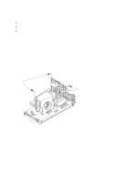
1. To remove the protective dust cover on the processor module, grasp and pull the cover evenly 3. To install processor module, insert A the module into the guides and press firmly and evenly into place to ensure the module is properly seated. B 2. To remove the protective dust cover on the system board, grasp the tab at the end of the cover and gently rock the cover back and forth while gently pulling it up NOTE: Replace the protective dust cover on the processor module being returned Figure 5-21. Processor Module and System Board Dust Covers Figure 5-22. J282 Processor Modules 5-26 Field Replaceable Units
-
 1
1 -
2
-
3
-
4
-
5
-
6
-
7
-
8
-
9
-
10
-
11
-
12
-
13
-
14
-
15
-
16
-
17
-
18
-
19
-
20
-
21
-
22
-
23
-
24
-
25
-
26
-
27
-
28
-
29
-
30
-
31
-
32
-
33
-
34
-
35
-
36
-
37
-
38
-
39
-
40
-
41
-
42
-
43
-
44
-
45
-
46
-
47
-
48
-
49
-
50
-
51
-
52
-
53
-
54
-
55
-
56
-
57
-
58
-
59
-
60
-
61
-
62
-
63
-
64
-
65
-
66
-
67
-
68
-
69
-
70
-
71
-
72
-
73
-
74
-
75
-
76
-
77
-
78
-
79
-
80
-
81
-
82
-
83
-
84
-
85
-
86
-
87
-
88
-
89
-
90
-
91
-
92
-
93
-
94
-
95
-
96
-
97
-
98
-
99
-
100
-
101
-
102
-
 103
103 -
 104
104 -
 105
105 -
 106
106 -
 107
107 -
 108
108 -
 109
109 -
 110
110 -
 111
111 -
 112
112 -
 113
113 -
114
-
115
-
116
-
117
-
118
-
119
-
120
-
121
-
122
-
123
-
124
-
125
-
126
-
127
-
128
-
129
-
130
-
131
-
132
-
133
-
134
-
135
-
136
-
137
-
138
-
139
-
140
-
141
-
142
-
143
-
144
-
145
-
146
-
147
-
148
-
149
-
150
-
151
-
152
-
153
-
154
-
155
-
156
-
157
-
158
-
159
-
160
-
161
-
162
-
163
-
164
-
165
-
166
-
167
-
168
-
169
-
170
-
171
-
172
 |
 |

5–26
Field Replaceable Units
A
2. To remove the protective dust cov-
er on the system board, grasp the tab
at the end of the cover and gently
rock the cover back and forth while
gently pulling it up
1. To remove the protective dust
cover on the processor module,
grasp and pull
the cover evenly
3. To install processor module, insert
the module into the guides and press
firmly and evenly into place to ensure
the module is properly seated.
B
NOTE: Replace the protective dust cover
on the processor module being returned
Figure 5–21.
Processor Module and System Board Dust Covers
Figure 5–22.
J282 Processor Modules