IBM 8676 Hardware Maintenance Manual - Page 82
Operator, information
 |
UPC - 087944770107
View all IBM 8676 manuals
Add to My Manuals
Save this manual to your list of manuals |
Page 82 highlights
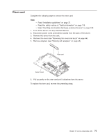
Operator information card Complete the following steps to remove the operator information card. Note: v Read "Installation guidelines" on page 37. v Read the safety notices at "Safety information" on page 119. v Read "Handling electrostatic discharge-sensitive devices" on page 122. 1. Turn off the server. 2. Disconnect all power cords and external cables from the back of the server; then, remove the server from the rack. 3. Remove the server cover and bezel (see "Removing the cover and bezel" on page 44). 4. Remove the hard disk drive residing in the right-hand bay, if any (see "Hard disk drives" on page 48). 5. Disconnect the operator information card cables from the system board. Note: The illustrations in this publication might differ slightly from your hardware. Tabs Operator information card 6. Gently pull the operator information card forward until it disengages from the two tabs on the chassis, making sure that any cables that are pulled slide smoothly. 7. Disconnect the cables from the rear of the operator information card. To replace the operator information card, connect the two cables to the rear of the card and slide it under the tabs on the chassis until it is firmly anchored. 72 xSeries 335 Type 8676, Type 8830: Hardware Maintenance Manual and Troubleshooting Guide
-
 1
1 -
2
-
3
-
4
-
5
-
6
-
7
-
8
-
9
-
10
-
11
-
12
-
13
-
14
-
15
-
16
-
17
-
18
-
19
-
20
-
21
-
22
-
23
-
24
-
25
-
26
-
27
-
28
-
29
-
30
-
31
-
32
-
33
-
34
-
35
-
36
-
37
-
38
-
39
-
40
-
41
-
42
-
43
-
44
-
45
-
46
-
47
-
48
-
49
-
50
-
51
-
52
-
53
-
54
-
55
-
56
-
57
-
58
-
59
-
60
-
61
-
62
-
63
-
64
-
65
-
66
-
67
-
68
-
69
-
70
-
71
-
72
-
73
-
74
-
75
-
76
-
 77
77 -
 78
78 -
 79
79 -
 80
80 -
 81
81 -
 82
82 -
 83
83 -
 84
84 -
 85
85 -
 86
86 -
 87
87 -
88
-
89
-
90
-
91
-
92
-
93
-
94
-
95
-
96
-
97
-
98
-
99
-
100
-
101
-
102
-
103
-
104
-
105
-
106
-
107
-
108
-
109
-
110
-
111
-
112
-
113
-
114
-
115
-
116
-
117
-
118
-
119
-
120
-
121
-
122
-
123
-
124
-
125
-
126
-
127
-
128
-
129
-
130
-
131
-
132
-
133
-
134
-
135
-
136
-
137
-
138
-
139
-
140
-
141
-
142
-
143
-
144
-
145
-
146
-
147
-
148
-
149
-
150
-
151
-
152
-
153
-
154
-
155
-
156
-
157
-
158
-
159
-
160
-
161
-
162
-
163
-
164
-
165
-
166
-
167
-
168
-
169
-
170
-
171
-
172
 |
 |
