IBM 8676 Hardware Maintenance Manual - Page 86
System, board
 |
UPC - 087944770107
View all IBM 8676 manuals
Add to My Manuals
Save this manual to your list of manuals |
Page 86 highlights
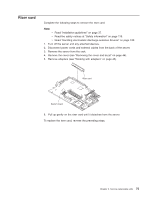
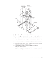
System board Complete the following steps to remove the system board. Note: v Read "Installation guidelines" on page 37. v Read the safety notices at "Safety information" on page 119. v Read "Handling electrostatic discharge-sensitive devices" on page 122. 1. Turn off the server and any attached devices. Note: When replacing the system board, you must either update the system with the latest firmware or restore the pre-existing firmware that the customer provides on a diskette or CD image. 2. Disconnect power cords and external cables from the back of the server. 3. Remove the server from the rack. 4. Remove the cover (see "Removing the cover and bezel" on page 44). 5. Remove the air baffle. 6. Remove all adapters (see "Working with adapters" on page 45). 7. Remove all fans (see "Replacing a fan assembly" on page 56). 8. Remove the riser card (see "Riser card" on page 75). 9. Remove the SCSI backplane (see "SCSI backplane" on page 74). 10. Disconnect all cables from the system board. 11. Remove all microprocessors and removable VRMs and set them aside on a static-protected surface for reinstallation (see "Installing a microprocessor" on page 52). 12. Remove the memory modules and set them aside on a static-protected surface for reinstallation (see "Installing memory modules" on page 51). Note: The illustrations in this publication might differ slightly from your hardware. 76 xSeries 335 Type 8676, Type 8830: Hardware Maintenance Manual and Troubleshooting Guide
-
 1
1 -
2
-
3
-
4
-
5
-
6
-
7
-
8
-
9
-
10
-
11
-
12
-
13
-
14
-
15
-
16
-
17
-
18
-
19
-
20
-
21
-
22
-
23
-
24
-
25
-
26
-
27
-
28
-
29
-
30
-
31
-
32
-
33
-
34
-
35
-
36
-
37
-
38
-
39
-
40
-
41
-
42
-
43
-
44
-
45
-
46
-
47
-
48
-
49
-
50
-
51
-
52
-
53
-
54
-
55
-
56
-
57
-
58
-
59
-
60
-
61
-
62
-
63
-
64
-
65
-
66
-
67
-
68
-
69
-
70
-
71
-
72
-
73
-
74
-
75
-
76
-
77
-
78
-
79
-
80
-
 81
81 -
 82
82 -
 83
83 -
 84
84 -
 85
85 -
 86
86 -
 87
87 -
 88
88 -
 89
89 -
 90
90 -
 91
91 -
92
-
93
-
94
-
95
-
96
-
97
-
98
-
99
-
100
-
101
-
102
-
103
-
104
-
105
-
106
-
107
-
108
-
109
-
110
-
111
-
112
-
113
-
114
-
115
-
116
-
117
-
118
-
119
-
120
-
121
-
122
-
123
-
124
-
125
-
126
-
127
-
128
-
129
-
130
-
131
-
132
-
133
-
134
-
135
-
136
-
137
-
138
-
139
-
140
-
141
-
142
-
143
-
144
-
145
-
146
-
147
-
148
-
149
-
150
-
151
-
152
-
153
-
154
-
155
-
156
-
157
-
158
-
159
-
160
-
161
-
162
-
163
-
164
-
165
-
166
-
167
-
168
-
169
-
170
-
171
-
172
 |
 |
