IBM 8676 Hardware Maintenance Manual - Page 91
FRU/action
 |
UPC - 087944770107
View all IBM 8676 manuals
Add to My Manuals
Save this manual to your list of manuals |
Page 91 highlights
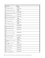
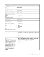
Note: See "System" on page 112 to determine which components should be replaced by a field service technician. Beep/symptom FRU/action 2-4-1 (Video failed; screen believed operable) v System board 3-1-1 (Timer tick interrupt failed) v System board 3-1-2 (Interval timer channel 2 failed) v System board 3-1-3 (RAM test failed above address OFFFFH)) 1. DIMM 2. System board 3-1-4 (Time-Of-Day clock failed) 1. Battery 2. System board 3-2-1 (Serial port failed) v System board 3-2-2 (Parallel port failed) v System board 3-2-3 (Math coprocessor test failed) 1. Microprocessor 2. System board 3-2-4 (Failure comparing CMOS memory size against actual) 1. DIMM 2. System board 3. Battery 3-3-1 (Memory size mismatch occurred.) 1. DIMM 2. System board 3. Battery 3-3-2 (Critical SMBUS error occurred) 1. Disconnect the server power cord from outlet, wait 30 seconds and retry. 2. System board. 3. DIMMs. 4. DASD backplane. 5. DASD power cable. 3-3-3 (No operational memory in system) Note: In some memory configurations, the 3-3-3 beep code might sound during POST followed by a blank display screen. If this 1. Install or reseat the memory modules, and then do a 3 boot reset. (For more information on a 3 boot reset, see "Using the Configuration/Setup Utility program" on page 9.) 2. DIMMs. 3. System board. occurs and the Boot Fail Count feature in the Start Options of the Configuration/Setup Utility is set to Enabled (its default setting), you must restart the server three times to force the system BIOS code to reset the memory connector or bank of connectors from Disabled to Enabled. Chapter 6. Symptom-to-FRU index 81
-
 1
1 -
2
-
3
-
4
-
5
-
6
-
7
-
8
-
9
-
10
-
11
-
12
-
13
-
14
-
15
-
16
-
17
-
18
-
19
-
20
-
21
-
22
-
23
-
24
-
25
-
26
-
27
-
28
-
29
-
30
-
31
-
32
-
33
-
34
-
35
-
36
-
37
-
38
-
39
-
40
-
41
-
42
-
43
-
44
-
45
-
46
-
47
-
48
-
49
-
50
-
51
-
52
-
53
-
54
-
55
-
56
-
57
-
58
-
59
-
60
-
61
-
62
-
63
-
64
-
65
-
66
-
67
-
68
-
69
-
70
-
71
-
72
-
73
-
74
-
75
-
76
-
77
-
78
-
79
-
80
-
81
-
82
-
83
-
84
-
85
-
 86
86 -
 87
87 -
 88
88 -
 89
89 -
 90
90 -
 91
91 -
 92
92 -
 93
93 -
 94
94 -
 95
95 -
 96
96 -
97
-
98
-
99
-
100
-
101
-
102
-
103
-
104
-
105
-
106
-
107
-
108
-
109
-
110
-
111
-
112
-
113
-
114
-
115
-
116
-
117
-
118
-
119
-
120
-
121
-
122
-
123
-
124
-
125
-
126
-
127
-
128
-
129
-
130
-
131
-
132
-
133
-
134
-
135
-
136
-
137
-
138
-
139
-
140
-
141
-
142
-
143
-
144
-
145
-
146
-
147
-
148
-
149
-
150
-
151
-
152
-
153
-
154
-
155
-
156
-
157
-
158
-
159
-
160
-
161
-
162
-
163
-
164
-
165
-
166
-
167
-
168
-
169
-
170
-
171
-
172
 |
 |
