IBM 8676 Hardware Maintenance Manual - Page 94
Diagnostic, error, codes
 |
UPC - 087944770107
View all IBM 8676 manuals
Add to My Manuals
Save this manual to your list of manuals |
Page 94 highlights
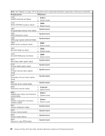
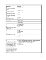
Note: See "System" on page 112 to determine which components should be replaced by a field service technician. Diagnostics panel LED FRU/action DASD (The LED located next to 1. Be sure the fans are operating correctly and the airflow is good. the drive bay that the failing drive is installed in is lit. Check the amber 2. SCSI backplane. drive LED for the failing hard drive.) PCI A (PCI/PCI-X slot 2 failed or 1. Adapter the integrated SCSI adapter failed.) 2. System board PCI B (An integrated Ethernet controller or PCI/PCI-X slot 1 failed.) 1. Adapter 2. System board PCI C (PCI/PCI-X slot 1 or the integrated video adapter failed.) 1. Adapter 2. System board NMI (Nonmaskable interrupt occurred.) 1. Restart the server. 2. Check the System Error Log. NON OPT (A PCI bus is not v Switch adapters, if possible. If adapters cannot be switched, they will operating at maximum efficiency.) continue to operate at lowered efficiency and light will remain lit. Diagnostic error codes Note: In the following error codes, if XXX is 000, 195, or 197, do not replace a FRU. The description for these error codes are: 000 The test passed. 195 The Esc key was pressed to stop the test. 197 Warning; a hardware failure might not have occurred. For all error codes, replace the FRU or take the action indicated. Note: See "System" on page 112 to determine which components should be replaced by a field service technician. Error code/symptom FRU/action 001-XXX-000 (Failed core tests) v System board 001-XXX-001 (Failed core tests) v System board 001-250-000 (Failed system board ECC) v System board 001-250-001 (Failed processor board ECC) v System board 005-XXX-000 (Failed video test) 1. Video adapter (if installed) 2. System board 011-XXX-000 (Failed COM1 serial port test) v Check loopback plug connected to externalized serial port. v Check cable from externalized port to system board. 011-XXX-001 (Failed COM2 serial port test) v Check loopback plug connected to externalized serial port. v Check cable from externalized port to system board. 84 xSeries 335 Type 8676, Type 8830: Hardware Maintenance Manual and Troubleshooting Guide
-
 1
1 -
2
-
3
-
4
-
5
-
6
-
7
-
8
-
9
-
10
-
11
-
12
-
13
-
14
-
15
-
16
-
17
-
18
-
19
-
20
-
21
-
22
-
23
-
24
-
25
-
26
-
27
-
28
-
29
-
30
-
31
-
32
-
33
-
34
-
35
-
36
-
37
-
38
-
39
-
40
-
41
-
42
-
43
-
44
-
45
-
46
-
47
-
48
-
49
-
50
-
51
-
52
-
53
-
54
-
55
-
56
-
57
-
58
-
59
-
60
-
61
-
62
-
63
-
64
-
65
-
66
-
67
-
68
-
69
-
70
-
71
-
72
-
73
-
74
-
75
-
76
-
77
-
78
-
79
-
80
-
81
-
82
-
83
-
84
-
85
-
86
-
87
-
88
-
 89
89 -
 90
90 -
 91
91 -
 92
92 -
 93
93 -
 94
94 -
 95
95 -
 96
96 -
 97
97 -
 98
98 -
 99
99 -
100
-
101
-
102
-
103
-
104
-
105
-
106
-
107
-
108
-
109
-
110
-
111
-
112
-
113
-
114
-
115
-
116
-
117
-
118
-
119
-
120
-
121
-
122
-
123
-
124
-
125
-
126
-
127
-
128
-
129
-
130
-
131
-
132
-
133
-
134
-
135
-
136
-
137
-
138
-
139
-
140
-
141
-
142
-
143
-
144
-
145
-
146
-
147
-
148
-
149
-
150
-
151
-
152
-
153
-
154
-
155
-
156
-
157
-
158
-
159
-
160
-
161
-
162
-
163
-
164
-
165
-
166
-
167
-
168
-
169
-
170
-
171
-
172
 |
 |
