Intel 521 Data Sheet - Page 29
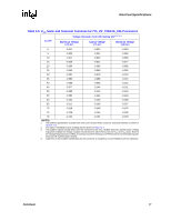
Table 2-10. V, Static and Transient Tolerance for 775_VR_CONFIG_04B Processors
 |
UPC - 683728199029
View all Intel 521 manuals
Add to My Manuals
Save this manual to your list of manuals |
Page 29 highlights
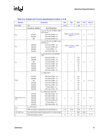
Electrical Specifications Table 2-10. VCC Static and Transient Tolerance for 775_VR_CONFIG_04B Processors Voltage Deviation from VID Setting (V)1, 2, 3, 4 ICC (A) Maximum Voltage 1.30 mΩ Typical Voltage 1.35 mΩ Minimum Voltage 1.40 mΩ 0 0.000 -0.019 -0.038 5 -0.007 -0.026 -0.045 10 -0.013 -0.033 -0.052 15 -0.020 -0.039 -0.059 20 -0.026 -0.046 -0.066 25 -0.033 -0.053 -0.073 30 -0.039 -0.060 -0.080 35 -0.046 -0.066 -0.087 40 -0.052 -0.073 -0.094 45 -0.059 -0.080 -0.101 50 -0.065 -0.087 -0.108 55 -0.072 -0.093 -0.115 60 -0.078 -0.100 -0.122 65 -0.085 -0.107 -0.129 70 -0.091 -0.114 -0.136 75 -0.098 -0.120 -0.143 80 -0.104 -0.127 -0.150 85 -0.111 -0.134 -0.157 90 -0.117 -0.141 -0.164 95 -0.124 -0.147 -0.171 100 -0.130 -0.154 -0.178 105 -0.137 -0.161 -0.185 110 -0.143 -0.168 -0.192 115 -0.150 -0.174 -0.199 119 -0.155 -0.180 -0.205 NOTES: 1. The loadline specification includes both static and transient limits except for overshoot allowed as shown in Section 2.12. 2. This table is intended to aid in reading discrete points on Figure 2-2. 3. The loadlines specify voltage limits at the die measured at the VCC_SENSE and VSS_SENSE lands. Voltage regulation feedback for voltage regulator circuits must be taken from processor VCC and VSS lands. Refer to the Voltage Regulator Down (VRD) 10.1 Design Guide For Desktop LGA775 Socket for socket loadline guidelines and VR implementation details. 4. Adherence to this loadline specification for the processor is required to ensure reliable processor operation. Datasheet 29
-
 1
1 -
2
-
3
-
4
-
5
-
6
-
7
-
8
-
9
-
10
-
11
-
12
-
13
-
14
-
15
-
16
-
17
-
18
-
19
-
20
-
21
-
22
-
23
-
 24
24 -
 25
25 -
 26
26 -
 27
27 -
 28
28 -
 29
29 -
 30
30 -
 31
31 -
 32
32 -
 33
33 -
 34
34 -
35
-
36
-
37
-
38
-
39
-
40
-
41
-
42
-
43
-
44
-
45
-
46
-
47
-
48
-
49
-
50
-
51
-
52
-
53
-
54
-
55
-
56
-
57
-
58
-
59
-
60
-
61
-
62
-
63
-
64
-
65
-
66
-
67
-
68
-
69
-
70
-
71
-
72
-
73
-
74
-
75
-
76
-
77
-
78
-
79
-
80
-
81
-
82
-
83
-
84
-
85
-
86
-
87
-
88
-
89
-
90
-
91
-
92
-
93
-
94
-
95
-
96
 |
 |
