Intel 521 Data Sheet - Page 76
Thermal Specifications and Design Considerations
 |
UPC - 683728199029
View all Intel 521 manuals
Add to My Manuals
Save this manual to your list of manuals |
Page 76 highlights
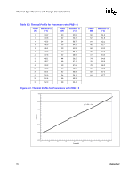
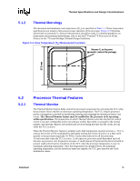
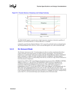
Thermal Specifications and Design Considerations The case temperature is defined at the geometric top center of the processor IHS. Analysis indicates that real applications are unlikely to cause the processor to consume maximum power dissipation for sustained periods of time. Intel recommends that complete thermal solution designs target the Thermal Design Power (TDP) indicated in Table 5-1 instead of the maximum processor power consumption. The Thermal Monitor feature is intended to help protect the processor in the unlikely event that an application exceeds the TDP recommendation for a sustained period of time. For more details on the usage of this feature, refer to Section 5.2. In all cases, the Thermal Monitor feature must be enabled for the processor to remain within specification. Table 5-1. Processor Thermal Specifications Processor Core Frequency Thermal Design Minimum TC Number (GHz) Power (W) (°C) Maximum TC (°C) Notes 520/521 530/531 540/541 550/551 550 560/561 570/571 2.80 (PRB = 0) 3 (PRB = 0) 3.20 (PRB = 0) 3.40 (PRB = 0) 3.40 (PRB = 1) 3.60 (PRB = 1) 3.80 (PRB = 1) 84 5 See Table 5-3 and Figure 5-2 1, 2 84 5 See Table 5-3 and Figure 5-2 1, 2 84 5 See Table 5-3 and Figure 5-2 1, 2 84 5 See Table 5-3 and Figure 5-2 1, 2 115 5 See Table 5-2 and Figure 5-1 1, 2 115 5 See Table 5-2 and Figure 5-1 1, 2 115 5 See Table 5-2 and Figure 5-1 1, 2 NOTES: 1. Thermal Design Power (TDP) should be used for processor thermal solution design targets. The TDP is not the maximum power that the processor can dissipate. 2. This table shows the maximum TDP for a given frequency range. Individual processors may have a lower TDP. Therefore, the maximum TC will vary depending on the TDP of the individual processor. Refer to thermal profile figure and associated table for the allowed combinations of power and TC. 76 Datasheet
-
 1
1 -
2
-
3
-
4
-
5
-
6
-
7
-
8
-
9
-
10
-
11
-
12
-
13
-
14
-
15
-
16
-
17
-
18
-
19
-
20
-
21
-
22
-
23
-
24
-
25
-
26
-
27
-
28
-
29
-
30
-
31
-
32
-
33
-
34
-
35
-
36
-
37
-
38
-
39
-
40
-
41
-
42
-
43
-
44
-
45
-
46
-
47
-
48
-
49
-
50
-
51
-
52
-
53
-
54
-
55
-
56
-
57
-
58
-
59
-
60
-
61
-
62
-
63
-
64
-
65
-
66
-
67
-
68
-
69
-
70
-
 71
71 -
 72
72 -
 73
73 -
 74
74 -
 75
75 -
 76
76 -
 77
77 -
 78
78 -
 79
79 -
 80
80 -
 81
81 -
82
-
83
-
84
-
85
-
86
-
87
-
88
-
89
-
90
-
91
-
92
-
93
-
94
-
95
-
96
 |
 |
