Intel 521 Data Sheet - Page 6

Tables

Page 6 highlights

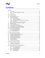
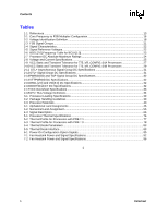
Contents Tables 1-1 References ...13 2-1 Core Frequency to FSB Multiplier Configuration 16 2-2 Voltage Identification Definition 18 2-3 FSB Signal Groups...21 2-4 Signal Characteristics ...22 2-5 Signal Reference Voltages ...22 2-6 BSEL[2:0] Frequency Table for BCLK[1:0 23 2-7 Processor DC Absolute Maximum Ratings 24 2-8 Voltage and Current Specifications 25 2-9 VCC Static and Transient Tolerance for 775_VR_CONFIG_04A Processors 27 2-10 VCC Static and Transient Tolerance for 775_VR_CONFIG_04B Processors 29 2-11 GTL+ Asynchronous Signal Group DC Specifications 31 2-12 GTL+ Signal Group DC Specifications 31 2-13 PWRGOOD and TAP Signal Group DC Specifications 32 2-14 VTTPWRGD DC Specifications 32 2-15 BSEL [2:0] and VID[5:0] DC Specifications 32 2-16 BOOTSELECT DC Specifications 32 2-17 VCC Overshoot Specifications 33 2-18 GTL+ Bus Voltage Definitions ...34 3-1 Processor Loading Specifications 39 3-2 Package Handling Guidelines ...39 3-3 Processor Materials ...40 4-1 Alphabetical Land Assignments 46 4-2 Numerical Land Assignment...56 4-3 Signal Description...66 5-1 Processor Thermal Specifications 76 5-2 Thermal Profile for Processors with PRB = 1 77 5-3 Thermal Profile for Processors with PRB = 0 78 5-4 Thermal Diode Parameters ...83 5-5 Thermal Diode Interface ...83 6-1 Power-On Configuration Option Signals 85 7-1 Fan Heatsink Power and Signal Specifications 92 7-2 Fan Heatsink Power and Signal Specifications 96 § 6 Datasheet

  • 1
  • 2
  • 3
  • 4
  • 5
  • 6
  • 7
  • 8
  • 9
  • 10
  • 11
  • 12
  • 13
  • 14
  • 15
  • 16
  • 17
  • 18
  • 19
  • 20
  • 21
  • 22
  • 23
  • 24
  • 25
  • 26
  • 27
  • 28
  • 29
  • 30
  • 31
  • 32
  • 33
  • 34
  • 35
  • 36
  • 37
  • 38
  • 39
  • 40
  • 41
  • 42
  • 43
  • 44
  • 45
  • 46
  • 47
  • 48
  • 49
  • 50
  • 51
  • 52
  • 53
  • 54
  • 55
  • 56
  • 57
  • 58
  • 59
  • 60
  • 61
  • 62
  • 63
  • 64
  • 65
  • 66
  • 67
  • 68
  • 69
  • 70
  • 71
  • 72
  • 73
  • 74
  • 75
  • 76
  • 77
  • 78
  • 79
  • 80
  • 81
  • 82
  • 83
  • 84
  • 85
  • 86
  • 87
  • 88
  • 89
  • 90
  • 91
  • 92
  • 93
  • 94
  • 95
  • 96

6
Datasheet
Contents
Tables
1-1 References
.................................................................................................................................
13
2-1
Core Frequency to FSB Multiplier Configuration
........................................................................
16
2-2
Voltage Identification Definition
..................................................................................................
18
2-3
FSB Signal Groups
.....................................................................................................................
21
2-4
Signal Characteristics
.................................................................................................................
22
2-5
Signal Reference Voltages
.........................................................................................................
22
2-6
BSEL[2:0] Frequency Table for BCLK[1:0]
.................................................................................
23
2-7
Processor DC Absolute Maximum Ratings
................................................................................
24
2-8
Voltage and Current Specifications
............................................................................................
25
2-9
VCC Static and Transient Tolerance for 775_VR_CONFIG_04A Processors
...........................
27
2-10VCC Static and Transient Tolerance for 775_VR_CONFIG_04B Processors
...........................
29
2-11 GTL+ Asynchronous Signal Group DC Specifications
..............................................................
31
2-12GTL+ Signal Group DC Specifications
.......................................................................................
31
2-13PWRGOOD and TAP Signal Group DC Specifications
..............................................................
32
2-14VTTPWRGD DC Specifications
..................................................................................................
32
2-15BSEL [2:0] and VID[5:0] DC Specifications
................................................................................
32
2-16BOOTSELECT DC Specifications
..............................................................................................
32
2-17VCC Overshoot Specifications
...................................................................................................
33
2-18GTL+ Bus Voltage Definitions
....................................................................................................
34
3-1
Processor Loading Specifications
..............................................................................................
39
3-2
Package Handling Guidelines
....................................................................................................
39
3-3
Processor Materials
....................................................................................................................
40
4-1
Alphabetical Land Assignments
.................................................................................................
46
4-2
Numerical Land Assignment
.......................................................................................................
56
4-3
Signal Description
.......................................................................................................................
66
5-1
Processor Thermal Specifications
..............................................................................................
76
5-2
Thermal Profile for Processors with PRB = 1
.............................................................................
77
5-3
Thermal Profile for Processors with PRB = 0
.............................................................................
78
5-4
Thermal Diode Parameters
........................................................................................................
83
5-5
Thermal Diode Interface
.............................................................................................................
83
6-1
Power-On Configuration Option Signals
.....................................................................................
85
7-1
Fan Heatsink Power and Signal Specifications
..........................................................................
92
7-2
Fan Heatsink Power and Signal Specifications
..........................................................................
96
ยง