Intel 521 Data Sheet - Page 5

Intel 521 - Pentium 4 521 2.8GHz 800MHz 1MB Socket 775 CPU Manual

Page 5 highlights

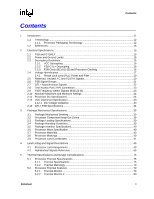
Contents Figures 2-1 Phase Lock Loop (PLL) Filter Requirements 19 2-2 VCC Static and Transient Tolerance for 775_VR_CONFIG_04A 28 2-3 VCC Static and Transient Tolerance for 775_VR_CONFIG_04B 30 2-4 VCC Overshoot Example Waveform 33 3-1 Processor Package Assembly Sketch 35 3-2 Processor Package Drawing 1 36 3-3 Processor Package Drawing 2 37 3-4 Processor Package Drawing 3 38 3-5 Processor Top-Side Marking Example 40 3-6 Processor Top-Side Marking Example for Processors Supporting Intel® EM64T 41 3-7 Processor Land Coordinates (Top View 42 4-1 Landout Diagram (Top View - Left Side 44 4-2 Landout Diagram (Top View - Right Side 45 5-1 Thermal Profile for Processors with PRB = 1 77 5-2 Thermal Profile for Processors with PRB = 0 78 5-3 Case Temperature (TC) Measurement Location 79 5-4 Thermal Monitor 2 Frequency and Voltage Ordering 81 6-1 Processor Low Power State Machine 87 7-1 Mechanical Representation of the Boxed Processor 89 7-2 Space Requirements for the Boxed Processor (Side View 90 7-3 Space Requirements for the Boxed Processor (Top View 90 7-4 Space Requirements for the Boxed Processor (Overall View 91 7-5 Boxed Processor Fan Heatsink Power Cable Connector Description 92 7-6 Baseboard Power Header Placement Relative to Processor Socket 93 7-7 Boxed Processor Fan Heatsink Airspace Keepout Requirements (Top View 94 7-8 Boxed Processor Fan Heatsink Airspace Keepout Requirements (Side View 94 7-9 Boxed Processor Fan Heatsink Set Points 95 Datasheet 5

  • 1
  • 2
  • 3
  • 4
  • 5
  • 6
  • 7
  • 8
  • 9
  • 10
  • 11
  • 12
  • 13
  • 14
  • 15
  • 16
  • 17
  • 18
  • 19
  • 20
  • 21
  • 22
  • 23
  • 24
  • 25
  • 26
  • 27
  • 28
  • 29
  • 30
  • 31
  • 32
  • 33
  • 34
  • 35
  • 36
  • 37
  • 38
  • 39
  • 40
  • 41
  • 42
  • 43
  • 44
  • 45
  • 46
  • 47
  • 48
  • 49
  • 50
  • 51
  • 52
  • 53
  • 54
  • 55
  • 56
  • 57
  • 58
  • 59
  • 60
  • 61
  • 62
  • 63
  • 64
  • 65
  • 66
  • 67
  • 68
  • 69
  • 70
  • 71
  • 72
  • 73
  • 74
  • 75
  • 76
  • 77
  • 78
  • 79
  • 80
  • 81
  • 82
  • 83
  • 84
  • 85
  • 86
  • 87
  • 88
  • 89
  • 90
  • 91
  • 92
  • 93
  • 94
  • 95
  • 96

Datasheet
5
Contents
Figures
2-1
Phase Lock Loop (PLL) Filter Requirements
..............................................................................
19
2-2
VCC Static and Transient Tolerance for 775_VR_CONFIG_04A
...............................................
28
2-3
VCC Static and Transient Tolerance for 775_VR_CONFIG_04B
...............................................
30
2-4
VCC Overshoot Example Waveform
..........................................................................................
33
3-1
Processor Package Assembly Sketch
........................................................................................
35
3-2
Processor Package Drawing 1
...................................................................................................
36
3-3
Processor Package Drawing 2
...................................................................................................
37
3-4
Processor Package Drawing 3
...................................................................................................
38
3-5
Processor Top-Side Marking Example
.......................................................................................
40
3-6
Processor Top-Side Marking Example for Processors Supporting Intel
®
EM64T
......................
41
3-7
Processor Land Coordinates (Top View)
....................................................................................
42
4-1
Landout Diagram (Top View – Left Side)
....................................................................................
44
4-2
Landout Diagram (Top View – Right Side)
.................................................................................
45
5-1
Thermal Profile for Processors with PRB = 1
.............................................................................
77
5-2
Thermal Profile for Processors with PRB = 0
.............................................................................
78
5-3
Case Temperature (TC) Measurement Location
........................................................................
79
5-4
Thermal Monitor 2 Frequency and Voltage Ordering
.................................................................
81
6-1
Processor Low Power State Machine
.........................................................................................
87
7-1
Mechanical Representation of the Boxed Processor
..................................................................
89
7-2
Space Requirements for the Boxed Processor (Side View)
.......................................................
90
7-3
Space Requirements for the Boxed Processor (Top View)
........................................................
90
7-4
Space Requirements for the Boxed Processor (Overall View)
...................................................
91
7-5
Boxed Processor Fan Heatsink Power Cable Connector Description
........................................
92
7-6
Baseboard Power Header Placement Relative to Processor Socket
.........................................
93
7-7
Boxed Processor Fan Heatsink Airspace Keepout Requirements (Top View)
...........................
94
7-8
Boxed Processor Fan Heatsink Airspace Keepout Requirements (Side View)
..........................
94
7-9
Boxed Processor Fan Heatsink Set Points
.................................................................................
95