Intel 521 Data Sheet - Page 60
TESTHI11, Power/Other, Input, Asynch GTL, RESERVED, Source Synch, Input/Output, Output, ADSTB0,
 |
UPC - 683728199029
View all Intel 521 manuals
Add to My Manuals
Save this manual to your list of manuals |
Page 60 highlights
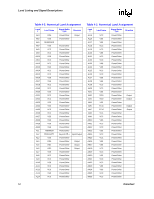
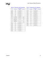
Land Listing and Signal Descriptions Table 4-2. Numerical Land Assignment Land # P1 P2 P3 P4 P5 P6 P7 P8 P23 P24 P25 P26 P27 P28 P29 P30 R1 R2 R3 R4 R5 R6 R7 R8 R23 R24 R25 R26 R27 R28 R29 R30 T1 T2 T3 T4 T5 T6 T7 T8 T23 Land Name TESTHI11 SMI# INIT# VSS RESERVED A4# VSS VCC VSS VSS VSS VSS VSS VSS VSS VSS FC2 VSS FERR#/PBE# A8# VSS ADSTB0# VSS VCC VSS VSS VSS VSS VSS VSS VSS VSS COMP1 FC4 VSS A11# A9# VSS VSS VCC VCC Signal Buffer Type Power/Other Asynch GTL+ Asynch GTL+ Power/Other Direction Input Input Input Source Synch Input/Output Power/Other Power/Other Power/Other Power/Other Power/Other Power/Other Power/Other Power/Other Power/Other Power/Other Power/Other Input Power/Other Asynch GTL+ Output Source Synch Input/Output Power/Other Source Synch Input/Output Power/Other Power/Other Power/Other Power/Other Power/Other Power/Other Power/Other Power/Other Power/Other Power/Other Power/Other Input Power/Other Input Power/Other Source Synch Input/Output Source Synch Input/Output Power/Other Power/Other Power/Other Power/Other Table 4-2. Numerical Land Assignment Land # T24 T25 T26 T27 T28 T29 T30 U1 U2 U3 U4 U5 U6 U7 U8 U23 U24 U25 U26 U27 U28 U29 U30 V1 V2 V3 V4 V5 V6 V7 V8 V23 V24 V25 V26 V27 V28 V29 V30 W1 W2 Land Name VCC VCC VCC VCC VCC VCC VCC VSS AP0# AP1# A13# A12# A10# VSS VCC VCC VCC VCC VCC VCC VCC VCC VCC MSID1 LL_ID0 VSS A15# A14# VSS VSS VCC VSS VSS VSS VSS VSS VSS VSS VSS MSID0 TESTHI12 Signal Buffer Type Direction Power/Other Power/Other Power/Other Power/Other Power/Other Power/Other Power/Other Power/Other Common Clock Input/Output Common Clock Input/Output Source Synch Input/Output Source Synch Input/Output Source Synch Input/Output Power/Other Power/Other Power/Other Power/Other Power/Other Power/Other Power/Other Power/Other Power/Other Power/Other Power/Other Output Power/Other Output Power/Other Source Synch Input/Output Source Synch Input/Output Power/Other Power/Other Power/Other Power/Other Power/Other Power/Other Power/Other Power/Other Power/Other Power/Other Power/Other Power/Other Output Power/Other Input 60 Datasheet
-
 1
1 -
2
-
3
-
4
-
5
-
6
-
7
-
8
-
9
-
10
-
11
-
12
-
13
-
14
-
15
-
16
-
17
-
18
-
19
-
20
-
21
-
22
-
23
-
24
-
25
-
26
-
27
-
28
-
29
-
30
-
31
-
32
-
33
-
34
-
35
-
36
-
37
-
38
-
39
-
40
-
41
-
42
-
43
-
44
-
45
-
46
-
47
-
48
-
49
-
50
-
51
-
52
-
53
-
54
-
 55
55 -
 56
56 -
 57
57 -
 58
58 -
 59
59 -
 60
60 -
 61
61 -
 62
62 -
 63
63 -
 64
64 -
 65
65 -
66
-
67
-
68
-
69
-
70
-
71
-
72
-
73
-
74
-
75
-
76
-
77
-
78
-
79
-
80
-
81
-
82
-
83
-
84
-
85
-
86
-
87
-
88
-
89
-
90
-
91
-
92
-
93
-
94
-
95
-
96
 |
 |
