Intel E3300 Data Sheet - Page 29
Phase Lock Loop PLL and Filter, BCLK[1:0] Specifications
 |
View all Intel E3300 manuals
Add to My Manuals
Save this manual to your list of manuals |
Page 29 highlights
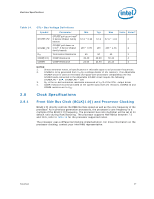
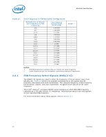
Electrical Specifications Table 16. BSEL[2:0] Frequency Table for BCLK[1:0] BSEL2 BSEL1 BSEL0 FSB Frequency L L L L L H L H H L H L H H L H H H H L H H L L Reserved Reserved Reserved 200 MHz Reserved Reserved Reserved Reserved 2.8.3 Phase Lock Loop (PLL) and Filter An on-die PLL filter solution will be implemented on the processor. The VCCPLL input is used for the PLL. Refer to Table 4 for DC specifications. 2.8.4 BCLK[1:0] Specifications Table 17. Front Side Bus Differential BCLK Specifications Symbol Parameter Min Typ Max Unit Figure Notes1 VL Input Low Voltage -0.30 N/A N/A V 3 VH Input High Voltage N/A N/A 1.15 V 3 VCROSS(abs) Absolute Crossing Point 0.300 N/A 0.550 V 3 2 VCROSS Range of Crossing Points N/A N/A 0.140 V 3 - VOS Overshoot N/A N/A 1.4 V 3 3 VUS Undershoot -0.300 N/A N/A V 3 3 VSWING Differential Output Swing 0.300 N/A N/A V 4 4 NOTES: 1. Unless otherwise noted, all specifications in this table apply to all processor frequencies. 2. Crossing voltage is defined as the instantaneous voltage value when the rising edge of BCLK0 equals the falling edge of BCLK1. 3. "Steady state" voltage, not including overshoot or undershoot. 4. Overshoot is defined as the absolute value of the maximum voltage. Undershoot is defined as the absolute value of the minimum voltage. 5. Measurement taken from differential waveform. Datasheet 29
-
 1
1 -
2
-
3
-
4
-
5
-
6
-
7
-
8
-
9
-
10
-
11
-
12
-
13
-
14
-
15
-
16
-
17
-
18
-
19
-
20
-
21
-
22
-
23
-
 24
24 -
 25
25 -
 26
26 -
 27
27 -
 28
28 -
 29
29 -
 30
30 -
 31
31 -
 32
32 -
 33
33 -
 34
34 -
35
-
36
-
37
-
38
-
39
-
40
-
41
-
42
-
43
-
44
-
45
-
46
-
47
-
48
-
49
-
50
-
51
-
52
-
53
-
54
-
55
-
56
-
57
-
58
-
59
-
60
-
61
-
62
-
63
-
64
-
65
-
66
-
67
-
68
-
69
-
70
-
71
-
72
-
73
-
74
-
75
-
76
-
77
-
78
-
79
-
80
-
81
-
82
-
83
-
84
-
85
-
86
-
87
-
88
-
89
-
90
-
91
-
92
-
93
-
94
-
95
-
96
-
97
-
98
-
99
-
100
 |
 |