Intel E3300 Data Sheet - Page 94
Boxed Processor Fan Heatsink Power Cable Connector Description, Table 29., Fan Heatsink
 |
View all Intel E3300 manuals
Add to My Manuals
Save this manual to your list of manuals |
Page 94 highlights
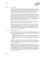
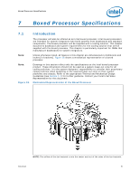
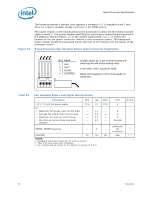
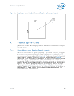
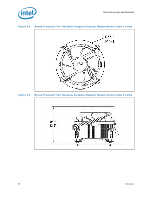
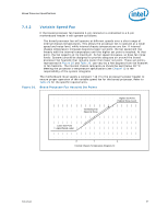
Boxed Processor Specifications Figure 22. The boxed processor's fanheat sink requires a constant +12 V supplied to pin 2 and does not support variable voltage control or 3-pin PWM control. The power header on the baseboard must be positioned to allow the fan heatsink power cable to reach it. The power header identification and location should be documented in the platform documentation, or on the system board itself. Figure 23 shows the location of the fan power connector relative to the processor socket. The baseboard power header should be positioned within 110 mm [4.33 inches] from the center of the processor socket. Boxed Processor Fan Heatsink Power Cable Connector Description Pin Signal 1 GND 2 +12 V 3 SENSE 4 CONTROL Straight square pin, 4-pin terminal housing with polarizing ribs and friction locking ramp. 0.100" pitch, 0.025" square pin width. Match with straight pin, friction lock header on mainboard. 12 34 Table 29. Fan Heatsink Power and Signal Specifications Description Min Typ +12 V: 12 volt fan power supply 11.4 12 IC: • Maximum fan steady-state current draw - 1.2 • Average fan steady-state current draw - 0.5 • Maximum fan start-up current draw - 2.2 • Fan start-up current draw maximum duration - 1.0 SENSE: SENSE frequency - 2 CONTROL 21 25 NOTES: 1. Baseboard should pull this pin up to 5 V with a resistor. 2. Open drain type, pulse width modulated. 3. Fan will have pull-up resistor for this signal to maximum of 5.25 V. Max 12.6 - - - - - 28 Unit V Notes - A A - A Second pulses per fan 1 revolution kHz 2, 3 94 Datasheet
-
 1
1 -
2
-
3
-
4
-
5
-
6
-
7
-
8
-
9
-
10
-
11
-
12
-
13
-
14
-
15
-
16
-
17
-
18
-
19
-
20
-
21
-
22
-
23
-
24
-
25
-
26
-
27
-
28
-
29
-
30
-
31
-
32
-
33
-
34
-
35
-
36
-
37
-
38
-
39
-
40
-
41
-
42
-
43
-
44
-
45
-
46
-
47
-
48
-
49
-
50
-
51
-
52
-
53
-
54
-
55
-
56
-
57
-
58
-
59
-
60
-
61
-
62
-
63
-
64
-
65
-
66
-
67
-
68
-
69
-
70
-
71
-
72
-
73
-
74
-
75
-
76
-
77
-
78
-
79
-
80
-
81
-
82
-
83
-
84
-
85
-
86
-
87
-
88
-
 89
89 -
 90
90 -
 91
91 -
 92
92 -
 93
93 -
 94
94 -
 95
95 -
 96
96 -
 97
97 -
 98
98 -
 99
99 -
100
 |
 |