Intel Q9400S Design Guidelines - Page 23
Example Thermal Profile
 |
UPC - 735858207973
View all Intel Q9400S manuals
Add to My Manuals
Save this manual to your list of manuals |
Page 23 highlights
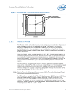
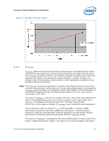
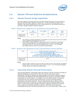
Processor Thermal/Mechanical Information Figure 3. Example Thermal Profile 2.2.3 TCONTROL TCONTROL defines the maximum operating temperature for the digital thermal sensor when the thermal solution fan speed is being controlled by the digital thermal sensor. The TCONTROL parameter defines a very specific processor operating region where fan speed can be reduced. This allows the system integrator a method to reduce the acoustic noise of the processor cooling solution, while maintaining compliance to the processor thermal specification. Note: The TCONTROL value for the processor is relative to the Thermal Control Circuit (TCC) activation set point which will be seen as 0 via the digital thermometer. As a result the TCONTROL value will always be a negative number. See Chapter 4 for the discussion of the thermal management logic and features and Chapter 6 on Intel® Quiet System Technology (Intel® QST). The value of TCONTROL is driven by a number of factors. One of the most significant of these is the processor idle power. As a result a processor with a high (closer to 0) TCONTROL will dissipate more power than a part with lower value (farther from 0, e.g., more negative number) of TCONTROL when running the same application. This is achieved in part by using the CA vs. RPM and RPM vs. Acoustics (dBA) performance curves from the Intel enabled thermal solution. A thermal solution designed to meet the thermal profile would be expected to provide similar acoustic performance for different parts with potentially different TCONTROL values. The value for TCONTROL is calculated by the system BIOS based on values read from a factory configured processor register. The result can be used to program a fan speed Thermal and Mechanical Design Guidelines 23
-
 1
1 -
2
-
3
-
4
-
5
-
6
-
7
-
8
-
9
-
10
-
11
-
12
-
13
-
14
-
15
-
16
-
17
-
 18
18 -
 19
19 -
 20
20 -
 21
21 -
 22
22 -
 23
23 -
 24
24 -
 25
25 -
 26
26 -
 27
27 -
 28
28 -
29
-
30
-
31
-
32
-
33
-
34
-
35
-
36
-
37
-
38
-
39
-
40
-
41
-
42
-
43
-
44
-
45
-
46
-
47
-
48
-
49
-
50
-
51
-
52
-
53
-
54
-
55
-
56
-
57
-
58
-
59
-
60
-
61
-
62
-
63
-
64
-
65
-
66
-
67
-
68
-
69
-
70
-
71
-
72
-
73
-
74
-
75
-
76
-
77
-
78
-
79
-
80
-
81
-
82
-
83
-
84
-
85
-
86
-
87
-
88
-
89
-
90
-
91
-
92
-
93
-
94
-
95
-
96
-
97
-
98
-
99
-
100
-
101
-
102
-
103
-
104
-
105
-
106
-
107
-
108
-
109
-
110
-
111
-
112
-
113
-
114
-
115
-
116
-
117
-
118
-
119
-
120
-
121
-
122
-
123
-
124
 |
 |
