Intel Q9400S Design Guidelines - Page 31
Processor Thermal Solution Performance, Assessment
 |
UPC - 735858207973
View all Intel Q9400S manuals
Add to My Manuals
Save this manual to your list of manuals |
Page 31 highlights
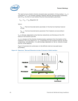
Thermal Metrology 3.1.1 3.2 Example The cooling performance, CA, is then defined using the principle of thermal characterization parameter described above: The case temperature TC-MAX and thermal design power TDP given in the processor datasheet. Define a target local ambient temperature at the processor, TA. Since the processor thermal profile applies to all processor frequencies, it is important to identify the worst case (lowest CA) for a targeted chassis characterized by TA to establish a design strategy. The following provides an illustration of how one might determine the appropriate performance targets. The example power and temperature numbers used here are not related to any specific Intel processor thermal specifications, and are for illustrative purposes only. Assume the TDP, as listed in the datasheet, is 100 W and the maximum case temperature from the thermal profile for 100W is 67 °C. Assume as well that the system airflow has been designed such that the local ambient temperature is 38 °C. Then the following could be calculated using equation 1 from above: CA = (TC,- TA) / TDP = (67 - 38) / 100 = 0.29 °C/W To determine the required heatsink performance, a heatsink solution provider would need to determine CS performance for the selected TIM and mechanical load configuration. If the heatsink solution were designed to work with a TIM material performing at CS 0.10 °C/W, solving for equation 2 from above, the performance of the heatsink would be: SA = CA CS = 0.29 0.10 = 0.19 °C/W Processor Thermal Solution Performance Assessment Thermal performance of a heatsink should be assessed using a thermal test vehicle (TTV) provided by Intel. The TTV is a stable heat source that the user can make accurate power measurement, whereas processors can introduce additional factors that can impact test results. In particular, the power level from actual processors varies significantly, even when running the maximum power application provided by Intel, due to variances in the manufacturing process. The TTV provides consistent power and power density for thermal solution characterization and results can be easily translated to real processor performance. Once the thermal solution is designed and validated with the TTV, it is strongly recommended to verify functionality of the thermal solution on real processors and on fully integrated systems. The Intel maximum power application enables steady power dissipation on a processor to assist in this testing. Thermal and Mechanical Design Guidelines 31
-
 1
1 -
2
-
3
-
4
-
5
-
6
-
7
-
8
-
9
-
10
-
11
-
12
-
13
-
14
-
15
-
16
-
17
-
18
-
19
-
20
-
21
-
22
-
23
-
24
-
25
-
 26
26 -
 27
27 -
 28
28 -
 29
29 -
 30
30 -
 31
31 -
 32
32 -
 33
33 -
 34
34 -
 35
35 -
 36
36 -
37
-
38
-
39
-
40
-
41
-
42
-
43
-
44
-
45
-
46
-
47
-
48
-
49
-
50
-
51
-
52
-
53
-
54
-
55
-
56
-
57
-
58
-
59
-
60
-
61
-
62
-
63
-
64
-
65
-
66
-
67
-
68
-
69
-
70
-
71
-
72
-
73
-
74
-
75
-
76
-
77
-
78
-
79
-
80
-
81
-
82
-
83
-
84
-
85
-
86
-
87
-
88
-
89
-
90
-
91
-
92
-
93
-
94
-
95
-
96
-
97
-
98
-
99
-
100
-
101
-
102
-
103
-
104
-
105
-
106
-
107
-
108
-
109
-
110
-
111
-
112
-
113
-
114
-
115
-
116
-
117
-
118
-
119
-
120
-
121
-
122
-
123
-
124
 |
 |
