Intel Q9400S Design Guidelines - Page 48
Fan Performance for Active Heatsink Thermal Solution - specs
 |
UPC - 735858207973
View all Intel Q9400S manuals
Add to My Manuals
Save this manual to your list of manuals |
Page 48 highlights
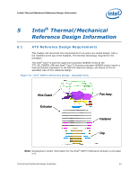
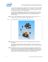
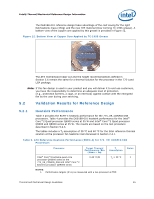
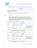
Intel® Thermal/Mechanical Reference Design Information 5.2.5 Fan Performance for Active Heatsink Thermal Solution The fan power requirements for proper operation are given Table 7. Table 7. Fan Electrical Performance Requirements Requirement Maximum Average fan current draw Fan start-up current draw Fan start-up current draw maximum duration Fan header voltage Tachometer output Tachometer output signal PWM signal input frequency PWM signal pull up in fan PWM signal current source PWM signal maximum voltage for logic low PWM compliant function Value 1.5 A 2.2 A 1.0 second 12 V ±5% 2 pulse per revolution Open-collector (open-drain) 21 kHz to 28 kHz 3.3 V (recommended max) 5.25 V (absolute max) Imax = 5 mA (short circuit current) VIL = 0.8 V RPM must be within spec for specified duty cycle In addition to comply with overall thermal requirements (Section 5.2.1), and the general environmental reliability requirements (Section 5.3) the fan should meet the following performance requirements: Mechanical wear out represents the highest risk reliability parameter for fans. The capability of the functional mechanical elements (ball bearing, shaft, and tower assembly) must be demonstrated to a minimum useful lifetime of 57,000 hours. In addition to passing the environmental reliability tests described in Section 5.3, the fan must demonstrate adequate performance after 7,500 on/off cycles with each cycle specified as 3 minutes on, 2 minutes off, at a temperature of 70 °C. See the Fan Specification for 4-wire PWM Controlled Fans for additional details on the fan specification. 48 Thermal and Mechanical Design Guidelines
-
 1
1 -
2
-
3
-
4
-
5
-
6
-
7
-
8
-
9
-
10
-
11
-
12
-
13
-
14
-
15
-
16
-
17
-
18
-
19
-
20
-
21
-
22
-
23
-
24
-
25
-
26
-
27
-
28
-
29
-
30
-
31
-
32
-
33
-
34
-
35
-
36
-
37
-
38
-
39
-
40
-
41
-
42
-
 43
43 -
 44
44 -
 45
45 -
 46
46 -
 47
47 -
 48
48 -
 49
49 -
 50
50 -
 51
51 -
 52
52 -
 53
53 -
54
-
55
-
56
-
57
-
58
-
59
-
60
-
61
-
62
-
63
-
64
-
65
-
66
-
67
-
68
-
69
-
70
-
71
-
72
-
73
-
74
-
75
-
76
-
77
-
78
-
79
-
80
-
81
-
82
-
83
-
84
-
85
-
86
-
87
-
88
-
89
-
90
-
91
-
92
-
93
-
94
-
95
-
96
-
97
-
98
-
99
-
100
-
101
-
102
-
103
-
104
-
105
-
106
-
107
-
108
-
109
-
110
-
111
-
112
-
113
-
114
-
115
-
116
-
117
-
118
-
119
-
120
-
121
-
122
-
123
-
124
 |
 |
