Intel Q9400S Design Guidelines - Page 28
System Integration Considerations
 |
UPC - 735858207973
View all Intel Q9400S manuals
Add to My Manuals
Save this manual to your list of manuals |
Page 28 highlights
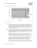
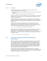
2.4.3 2.5 Processor Thermal/Mechanical Information ATX Thermal Design Suggestions or microATX Thermal Design Suggestions or Balanced Technology Extended (BTX) System Design Guide v1.0 documents available on the http://www.formfactors.org/ web site. In addition to passive heatsinks, fan heatsinks and system fans are other solutions that exist for cooling integrated circuit devices. For example, ducted blowers, heat pipes and liquid cooling are all capable of dissipating additional heat. Due to their varying attributes, each of these solutions may be appropriate for a particular system implementation. To develop a reliable, cost-effective thermal solution, thermal characterization and simulation should be carried out at the entire system level, accounting for the thermal requirements of each component. In addition, acoustic noise constraints may limit the size, number, placement, and types of fans that can be used in a particular design. To ease the burden on thermal solutions, the Thermal Monitor feature and associated logic have been integrated into the silicon of the processor. By taking advantage of the Thermal Monitor feature, system designers may reduce thermal solution cost by designing to TDP instead of maximum power. Thermal Monitor attempts to protect the processor during sustained workload above TDP. Implementation options and recommendations are described in Chapter 4. Summary In summary, considerations in heatsink design include: The local ambient temperature TA at the heatsink, which is a function of chassis design. The thermal design power (TDP) of the processor, and the corresponding maximum TC as calculated from the thermal profile. These parameters are usually combined in a single lump cooling performance parameter, CA (case to air thermal characterization parameter). More information on the definition and the use of CA is given Section 3.13.1. Heatsink interface to IHS surface characteristics, including flatness and roughness. The performance of the thermal interface material used between the heatsink and the IHS. The required heatsink clip static load, between 18 lbf to 70 lbf throughout the life of the product (Refer to Section 2.1.2.2 for further information). Surface area of the heatsink. Heatsink material and technology. Volume of airflow over the heatsink surface area. Development of airflow entering and within the heatsink area. Physical volumetric constraints placed by the system System Integration Considerations Manufacturing with Intel® Components using 775-Land LGA Package and LGA775 Socket documentation provides Best Known Methods for all aspects LGA775 socket based platforms and systems manufacturing. Of particular interest for package and heatsink installation and removal is the System Assembly module. A video covering system integration is also available. Contact your Intel field sales representative for further information. § 28 Thermal and Mechanical Design Guidelines
-
 1
1 -
2
-
3
-
4
-
5
-
6
-
7
-
8
-
9
-
10
-
11
-
12
-
13
-
14
-
15
-
16
-
17
-
18
-
19
-
20
-
21
-
22
-
 23
23 -
 24
24 -
 25
25 -
 26
26 -
 27
27 -
 28
28 -
 29
29 -
 30
30 -
 31
31 -
 32
32 -
 33
33 -
34
-
35
-
36
-
37
-
38
-
39
-
40
-
41
-
42
-
43
-
44
-
45
-
46
-
47
-
48
-
49
-
50
-
51
-
52
-
53
-
54
-
55
-
56
-
57
-
58
-
59
-
60
-
61
-
62
-
63
-
64
-
65
-
66
-
67
-
68
-
69
-
70
-
71
-
72
-
73
-
74
-
75
-
76
-
77
-
78
-
79
-
80
-
81
-
82
-
83
-
84
-
85
-
86
-
87
-
88
-
89
-
90
-
91
-
92
-
93
-
94
-
95
-
96
-
97
-
98
-
99
-
100
-
101
-
102
-
103
-
104
-
105
-
106
-
107
-
108
-
109
-
110
-
111
-
112
-
113
-
114
-
115
-
116
-
117
-
118
-
119
-
120
-
121
-
122
-
123
-
124
 |
 |
