Intel Q9400S Design Guidelines - Page 71
Load Cell Installation in Machined Heatsink Base Pocket Side View, Preload
 |
UPC - 735858207973
View all Intel Q9400S manuals
Add to My Manuals
Save this manual to your list of manuals |
Page 71 highlights
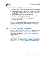
Heatsink Clip Load Metrology Figure 27. Load Cell Installation in Machined Heatsink Base Pocket (Side View) Height of pocket ~ height of selected load cell Wax to maintain load cell in position during heatsink installation Load cell protrusion (Note: to be optimized depending on assembly stiffness) Figure 28. Preload Test Configuration Preload Fixture (copper core with milled out pocket) Load Cells (3x) Thermal and Mechanical Design Guidelines 71
-
 1
1 -
2
-
3
-
4
-
5
-
6
-
7
-
8
-
9
-
10
-
11
-
12
-
13
-
14
-
15
-
16
-
17
-
18
-
19
-
20
-
21
-
22
-
23
-
24
-
25
-
26
-
27
-
28
-
29
-
30
-
31
-
32
-
33
-
34
-
35
-
36
-
37
-
38
-
39
-
40
-
41
-
42
-
43
-
44
-
45
-
46
-
47
-
48
-
49
-
50
-
51
-
52
-
53
-
54
-
55
-
56
-
57
-
58
-
59
-
60
-
61
-
62
-
63
-
64
-
65
-
 66
66 -
 67
67 -
 68
68 -
 69
69 -
 70
70 -
 71
71 -
 72
72 -
 73
73 -
 74
74 -
 75
75 -
 76
76 -
77
-
78
-
79
-
80
-
81
-
82
-
83
-
84
-
85
-
86
-
87
-
88
-
89
-
90
-
91
-
92
-
93
-
94
-
95
-
96
-
97
-
98
-
99
-
100
-
101
-
102
-
103
-
104
-
105
-
106
-
107
-
108
-
109
-
110
-
111
-
112
-
113
-
114
-
115
-
116
-
117
-
118
-
119
-
120
-
121
-
122
-
123
-
124
 |
 |

Heatsink Clip Load Metrology
Thermal and Mechanical Design Guidelines
71
Figure 27. Load Cell Installation in Machined Heatsink Base Pocket (Side View)
Figure 28. Preload Test Configuration
Load Cells (3x)
Preload Fixture (copper
core with milled out pocket)
Wax to maintain load cell in
position during heatsink
installation
Height of pocket
~ height of
selected load
cell
Load cell protrusion
(Note: to be optimized depending on assembly
stiffness)