Lenovo ThinkPad 600X TP 600E User's Reference - Page 19
Rear View of the Computer, where you connect
 |
View all Lenovo ThinkPad 600X manuals
Add to My Manuals
Save this manual to your list of manuals |
Page 19 highlights
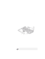
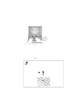
Identifying the Hardware Features Rear View of the Computer 1 The security keyhole is used with a mechanical lock. 2 The modem connector is used for connecting your computer to a telephone line. 3 The power switch turns the computer on and off. 4 The reset switch is used to power the computer off if an application hangs or if the computer will not accept any input. Use the tip of a pen to press this switch. 5 The universal serial bus (USB) connector allows you to connect any device that conforms to the USB interface. Many recent digital devices comply to this new standard. 6 The power jack is where the AC Adapter cable is connected. 7 The serial connector is where you connect a 9-pin, serial-device cable. 8 The system-expansion connector (240-pin) allows you to connect a port replicator or docking station. 9 The parallel connector is where you connect a parallel-printer signal cable. 1 The external-monitor connector is where you attach an external monitor (CRT). 11 The external-input-device connector is used to attach a mouse, an external keyboard, or an external numeric keypad to the computer. Bottom View of the Computer 1 The UltraslimBay device lock is a lock for the device in the UltraslimBay. 2 When the bay LED is on, the system is in use. Do not remove a bay device. 3 The memory-slot cover covers the memory slot. 4 Each of the memory slots accepts an SDRAM dual inline memory module (DIMM) option. 5 The battery-pack latch locks or releases the battery pack. 6 The serial number label identifies your computer. You need this number to get help. 7 Put your name plate here. 8 To remove the hard disk, loosen this hard disk drive screw. You can use the security screw shipped with your computer as a hard disk screw. 9 The battery pack is a built-in power source for the computer. Chapter 1. Getting Familiar with Your Computer 5
-
 1
1 -
2
-
3
-
4
-
5
-
6
-
7
-
8
-
9
-
10
-
11
-
12
-
13
-
 14
14 -
 15
15 -
 16
16 -
 17
17 -
 18
18 -
 19
19 -
 20
20 -
 21
21 -
 22
22 -
 23
23 -
 24
24 -
25
-
26
-
27
-
28
-
29
-
30
-
31
-
32
-
33
-
34
-
35
-
36
-
37
-
38
-
39
-
40
-
41
-
42
-
43
-
44
-
45
-
46
-
47
-
48
-
49
-
50
-
51
-
52
-
53
-
54
-
55
-
56
-
57
-
58
-
59
-
60
-
61
-
62
-
63
-
64
-
65
-
66
-
67
-
68
-
69
-
70
-
71
-
72
-
73
-
74
-
75
-
76
-
77
-
78
-
79
-
80
-
81
-
82
-
83
-
84
-
85
-
86
-
87
-
88
-
89
-
90
-
91
-
92
-
93
-
94
-
95
-
96
-
97
-
98
-
99
-
100
-
101
-
102
-
103
-
104
-
105
-
106
-
107
-
108
-
109
-
110
-
111
-
112
-
113
-
114
-
115
-
116
-
117
-
118
-
119
-
120
-
121
-
122
-
123
-
124
-
125
-
126
-
127
-
128
-
129
-
130
-
131
-
132
-
133
-
134
-
135
-
136
-
137
-
138
-
139
-
140
-
141
-
142
-
143
-
144
-
145
-
146
-
147
-
148
-
149
-
150
-
151
-
152
-
153
-
154
-
155
-
156
-
157
-
158
-
159
-
160
-
161
-
162
-
163
-
164
-
165
-
166
-
167
-
168
-
169
-
170
-
171
-
172
-
173
-
174
-
175
-
176
-
177
-
178
-
179
-
180
-
181
-
182
-
183
-
184
-
185
-
186
-
187
-
188
-
189
-
190
-
191
 |
 |
