Netgear FWAG114 FWAG114 Reference Manual - Page 132
Ethernet Cabling
 |
UPC - 606449026955
View all Netgear FWAG114 manuals
Add to My Manuals
Save this manual to your list of manuals |
Page 132 highlights
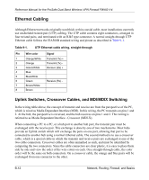
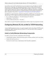
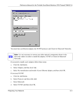
Reference Manual for the ProSafe Dual Band Wireless VPN Firewall FWAG114 Ethernet Cabling Although Ethernet networks originally used thick or thin coaxial cable, most installations currently use unshielded twisted pair (UTP) cabling. The UTP cable contains eight conductors, arranged in four twisted pairs, and terminated with an RJ45 type connector. A normal straight-through UTP Ethernet cable follows the EIA568B standard wiring and pinout as described in Table 9-1. Table 9-1. UTP Ethernet cable wiring, straight-through Pin Wire color Signal 1 Orange/White Transmit (Tx) + 2 Orange Transmit (Tx) - 3 Green/White Receive (Rx) + 4 Blue 5 Blue/White 6 Green Receive (Rx) - 7 Brown/White 8 Brown Uplink Switches, Crossover Cables, and MDI/MDIX Switching In the wiring table above, the concept of transmit and receive are from the perspective of the PC, which is wired as Media Dependant Interface (MDI). In this wiring, the PC transmits on pins 1 and 2. At the hub, the perspective is reversed, and the hub receives on pins 1 and 2. This wiring is referred to as Media Dependant Interface - Crossover (MDI-X). When connecting a PC to a PC, or a hub port to another hub port, the transmit pair must be exchanged with the receive pair. This exchange is done by one of two mechanisms. Most hubs provide an Uplink switch which will exchange the pairs on one port, allowing that port to be connected to another hub using a normal Ethernet cable. The second method is to use a crossover cable, which is a special cable in which the transmit and receive pairs are exchanged at one of the two cable connectors. Crossover cables are often unmarked as such, and must be identified by comparing the two connectors. Since the cable connectors are clear plastic, it is easy to place them side by side and view the order of the wire colors on each. On a straight-through cable, the color order will be the same on both connectors. On a crossover cable, the orange and blue pairs will be exchanged from one connector to the other. B-12 Network, Routing, Firewall, and Basics
-
 1
1 -
2
-
3
-
4
-
5
-
6
-
7
-
8
-
9
-
10
-
11
-
12
-
13
-
14
-
15
-
16
-
17
-
18
-
19
-
20
-
21
-
22
-
23
-
24
-
25
-
26
-
27
-
28
-
29
-
30
-
31
-
32
-
33
-
34
-
35
-
36
-
37
-
38
-
39
-
40
-
41
-
42
-
43
-
44
-
45
-
46
-
47
-
48
-
49
-
50
-
51
-
52
-
53
-
54
-
55
-
56
-
57
-
58
-
59
-
60
-
61
-
62
-
63
-
64
-
65
-
66
-
67
-
68
-
69
-
70
-
71
-
72
-
73
-
74
-
75
-
76
-
77
-
78
-
79
-
80
-
81
-
82
-
83
-
84
-
85
-
86
-
87
-
88
-
89
-
90
-
91
-
92
-
93
-
94
-
95
-
96
-
97
-
98
-
99
-
100
-
101
-
102
-
103
-
104
-
105
-
106
-
107
-
108
-
109
-
110
-
111
-
112
-
113
-
114
-
115
-
116
-
117
-
118
-
119
-
120
-
121
-
122
-
123
-
124
-
125
-
126
-
 127
127 -
 128
128 -
 129
129 -
 130
130 -
 131
131 -
 132
132 -
 133
133 -
 134
134 -
 135
135 -
 136
136 -
 137
137 -
138
-
139
-
140
-
141
-
142
-
143
-
144
-
145
-
146
-
147
-
148
-
149
-
150
-
151
-
152
-
153
-
154
-
155
-
156
-
157
-
158
-
159
-
160
-
161
-
162
-
163
-
164
-
165
-
166
-
167
-
168
-
169
-
170
-
171
-
172
-
173
-
174
-
175
-
176
-
177
-
178
-
179
-
180
-
181
-
182
-
183
-
184
-
185
-
186
-
187
-
188
-
189
-
190
-
191
-
192
 |
 |
