Panasonic WVNP472 WVNP472 User Guide - Page 10
Connections, Power-in Connections, Video Cable Connections, Control Terminal Connections
 |
View all Panasonic WVNP472 manuals
Add to My Manuals
Save this manual to your list of manuals |
Page 10 highlights
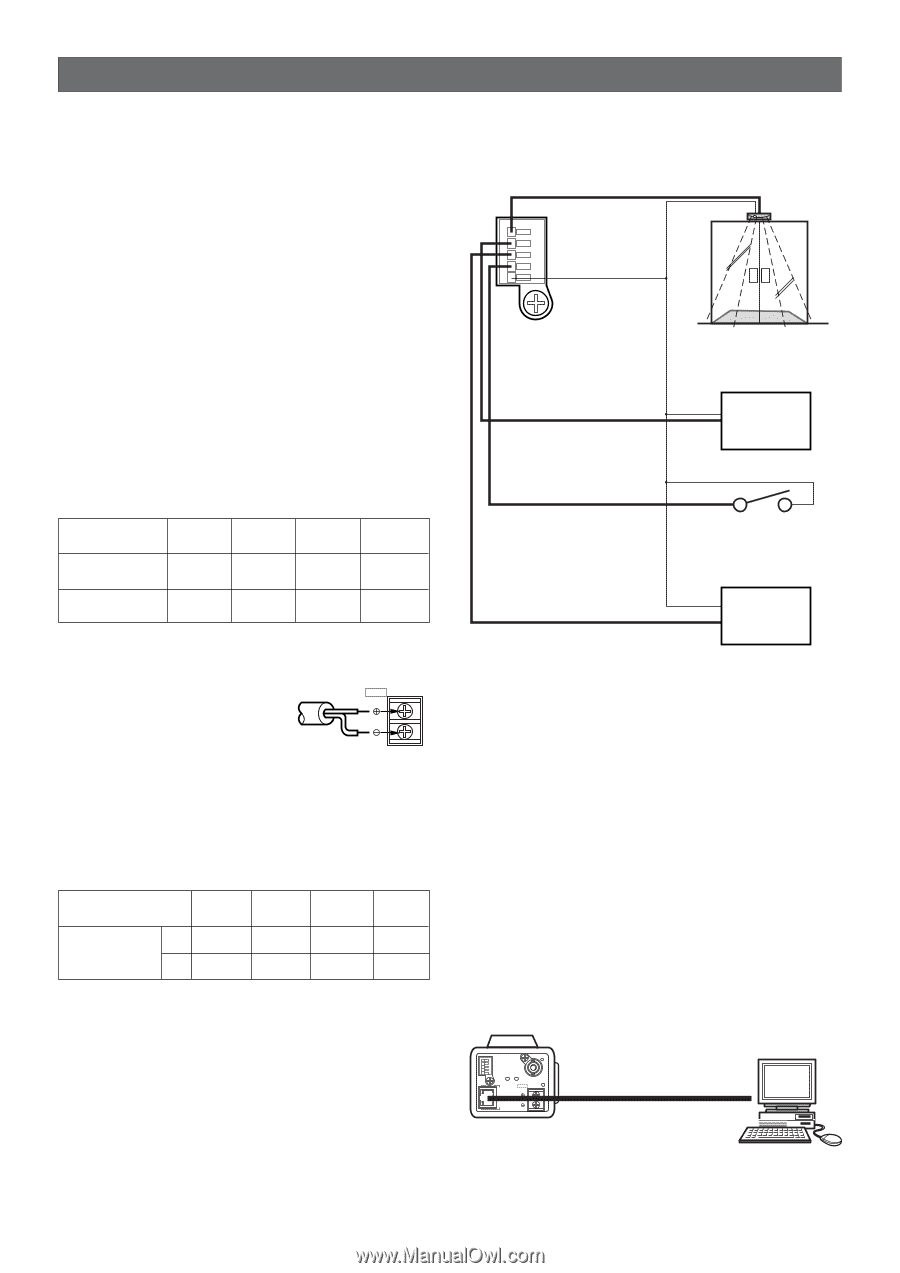
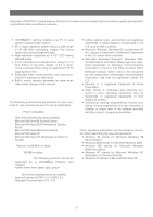
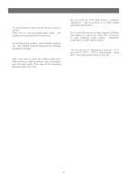
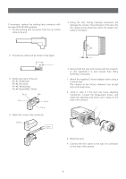
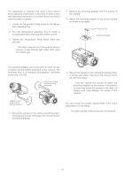
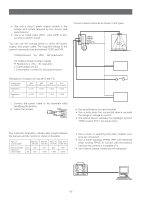
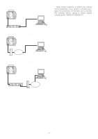
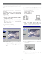
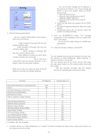
CONNECTIONS Power-in Connections Notes: • Use only a class-2 power supply suitable to the voltage and current required by the camera. See specifications. • Use a UL listed cable (VW-1, style 1007) to prevent fire or electric shock. You can use the formula below to select the power supply, and power cable. The supplied voltage to the power-in terminals must be between 10.8V and 16V. 10.8V(minimum) ≤ VA - 2RLI ≤ 16V (maximum) VA: Output voltage of power supply R: Resistance (Ω/m) (Ω/ft), see table L: Cable length (m) (ft) I: Consumption current (A), see specifications Control Terminal Connections Connect relevant devices as shown in the figure. ALARM IN ALARM IN ALARM OUT AUX OUT DAY/NIGHT IN GND Sensor ALARM OUT Recording device e.g. VCR Resistance of copper wire [at 20 °C (68 °F)] Copper wire size (AWG) Resistance Ω/m Resistance Ω/ft #24 #22 #20 #18 (0.22 mm2) (0.33 mm2) (0.52 mm2) (0.83 mm2) 0.078 0.050 0.030 0.018 0.026 0.017 0.010 0.006 1. Connect the power cable to the terminals while identifying the polarity. 2. Fasten the screws. DC 12V IN 12 V DC (10.8 V - 16 V) Video Cable Connections The maximum extensible coaxial cable length between the camera and the monitor is shown in the table. Type of coaxial cable Recommended maximum cable length RG-59/U RG-6/U RG-11/U RG-15/U (3C-2V) (5C-2V) (7C-2V) (10C-2V) (m) 250 500 600 800 (ft) 825 1 650 1 980 2 640 DAY/NIGHT IN AUX OUT Optical sensor ON: B/W, OFF: Color Aux devices e.g. lamp Notes: • See specifications for each terminal. • Use a relay when the connected device exceeds the ratings in voltage or current. • The optical sensor validates the Day/Night function if B/W is set to EXT in the setup menu. Network Connections Network Connection Types • Use a router or switching hub when multiple cameras are connected. • Use a router handling PPPoE (PPP over Ethernet) when running PPPoE to connect with the Internet, because the camera is incapable of it. • Use network cables complying with category5. • Direct Connection to PC (Type 1) ALARM IN ALARM OUT AUX OUT DAY/NIGHT IN GND A RCV B VIDEO OUT DC 12V POWER IN 10BASE-T/ 100BASE-TX LINK Network Cable (Cross type) PC -10-
-
 1
1 -
2
-
3
-
4
-
 5
5 -
 6
6 -
 7
7 -
 8
8 -
 9
9 -
 10
10 -
 11
11 -
 12
12 -
 13
13 -
 14
14 -
 15
15 -
16
-
17
-
18
-
19
-
20
-
21
-
22
-
23
-
24
-
25
-
26
-
27
-
28
-
29
-
30
-
31
-
32
-
33
-
34
-
35
-
36
-
37
-
38
-
39
-
40
-
41
-
42
-
43
-
44
-
45
-
46
-
47
 |
 |