Panasonic WVNP472 WVNP472 User Guide - Page 7
Major Operating Controls And Their Functions, Day/night In: Optical Sensor, Gnd: Signal
 |
View all Panasonic WVNP472 manuals
Add to My Manuals
Save this manual to your list of manuals |
Page 7 highlights
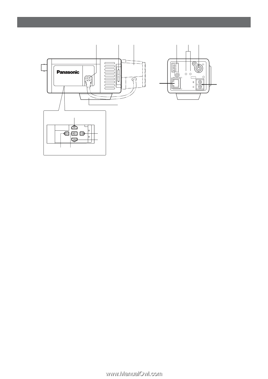
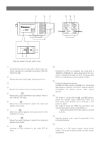
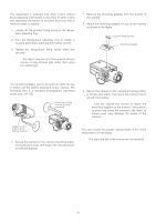
MAJOR OPERATING CONTROLS AND THEIR FUNCTIONS q w e !1 !2 !3 WV -NP472 !0 ALARM IN ALARM OUT AUX OUT DAY/NIGHT IN GND A RCV B VIDEO OUT DC 12V POWER IN 10BASE-T/ 100BASE-TX LINK !4 r u i t yo Slide the panel to the left until it locks. q Auto Iris Lens Connector Connects the auto iris lens with a 4-pin male connector supplied as a standard accessory (Part No. YFE4191J100). w Flange-back Adjusting Ring & Screw Adjusts the back focal length and picture focus. e Lens (Option) r Camera Mounting Adapter Mounts the camera onto a mounting bracket. t Down Button (K) Moves the cursor downward and selects items in the CAM SET UP menu. y Left Button (L) Moves the cursor leftward, selects the mode and adjusts some levels. u Up Button (J) Moves the cursor upward and selects items in the CAM SET UP menu. i Right Button (M) Moves the cursor rightward, selects the mode and adjusts some levels. o Set Button (I) Activates an item selected in the CAM SET UP menu. !0 Network Port with Indicators (10BASET/100BASE-TX/RCV/LINK) Connects to a PC or a network via a hub with a 10BASE-T/100BASE-TX cable attached RJ-45 connector. Indicators will light up while receiving data (RCV) or establishing communications (LINK). !1 Control Terminals Connects respective devices. ALARM IN: Alarm sensor, ALARM OUT: Recording device/alarm indicator, AUX OUT: External device, DAY/NIGHT IN: Optical sensor, GND: Signal ground !2 Reset Button (A, B) The button A, along with the J and K buttons, resets the network setup parameters when you hold down these buttons for 6 seconds in the power-on state. The button B resets the HTML files and alarm mail setup in the same manner as the button A. Note: Never press both the reset buttons A and B at a time. !3 Video Output Connector (VIDEO OUT) Supplies analog video signal (composite) to the connected device. !4 Power In Terminal and Power Indicator (DC 12V IN, POWER) Connects to a DC power supply using proper cables. The power indicator lights up when power is supplied. -7-
-
 1
1 -
 2
2 -
 3
3 -
 4
4 -
 5
5 -
 6
6 -
 7
7 -
 8
8 -
 9
9 -
 10
10 -
 11
11 -
 12
12 -
13
-
14
-
15
-
16
-
17
-
18
-
19
-
20
-
21
-
22
-
23
-
24
-
25
-
26
-
27
-
28
-
29
-
30
-
31
-
32
-
33
-
34
-
35
-
36
-
37
-
38
-
39
-
40
-
41
-
42
-
43
-
44
-
45
-
46
-
47
 |
 |