SanDisk SDCFH-004G Product Manual - Page 23
SanDisk CompactFlash Card OEM Product Manual, Interface Description, Signal Name, Description
 |
UPC - 878587001044
View all SanDisk SDCFH-004G manuals
Add to My Manuals
Save this manual to your list of manuals |
Page 23 highlights
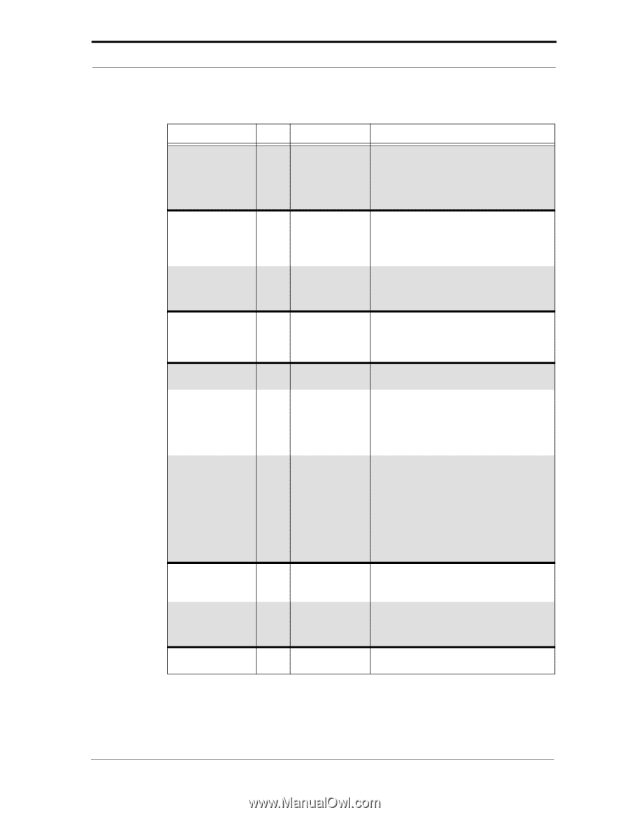
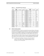
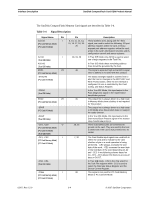
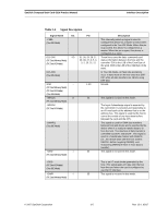
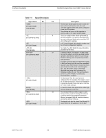
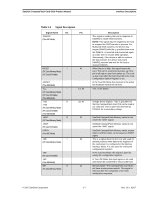
SanDisk CompactFlash Card OEM Product Manual Interface Description Table 3-4 Signal Description Signal Name Dir. Pin Description -CSEL (True IDE Mode) This internally pulled up signal is used to configure this device as a master or slave when configured in the True IDE Mode. When this pin is grounded, this device is configured as a master. When the pin is open, this device is configured as a slave. D15-D00 I/O 31, 30, 29, 28, 27, These lines carry the data, commands and (PC Card Memory Mode) (PC Card I/O Mode) 49, 48, 47, 6, 5, 4, 3, 2, 23, 22, 21 status information between the host and the controller. D00 is the LSB of the Even Byte of the word. D08 is the LSB of the Odd Byte of the word. D15-D00 (True IDE Mode) In True IDE Mode, all Task File operations occur in byte mode on the low order bus D00 D07 while all data transfers are 16 bits using D00-D15. GND -- (PC Card Memory Mode) (PC Card I/O Mode) (True IDE Mode) 1, 50 Ground. -INPACK O (PC Card Memory Mode) 43 This signal is not used in this mode. -INPACK (PC Card I/O Mode) The Input Acknowledge signal is asserted by the card when it is selected and responding to an I/O read cycle at the address that is on the address bus. This signal is used by the host to control the enable of any input data buffers between the card and the CPU. -DMARQ (True IDE Mode) This signal is used for DMA data transfers between host and device and is asserted by the device when it is ready to transfer data to or from the host. The direction of data transfer is controlled by DIOR- and DIOW-. This signal is used in a handshake manner with DMACK(i.e., the device waits until the host asserts DMACK- before negating DMARQ, and reasserting DMARQ if there is more data to transfer). -IORD I 34 This signal is not used in this mode. (PC Card Memory Mode) -IORD (PC Card I/O Mode) (True IDE Mode) -IOWR I (PC Card Memory Mode) This is an I/O read strobe generated by the host. This signal gates I/O data onto the bus from the card when the card is configured to use the I/O interface. 35 This signal is not used in this mode. © 2007 SanDisk Corporation 3-5 Rev. 12.0, 02/07
-
 1
1 -
2
-
3
-
4
-
5
-
6
-
7
-
8
-
9
-
10
-
11
-
12
-
13
-
14
-
15
-
16
-
17
-
 18
18 -
 19
19 -
 20
20 -
 21
21 -
 22
22 -
 23
23 -
 24
24 -
 25
25 -
 26
26 -
 27
27 -
 28
28 -
29
-
30
-
31
-
32
-
33
-
34
-
35
-
36
-
37
-
38
-
39
-
40
-
41
-
42
-
43
-
44
-
45
-
46
-
47
-
48
-
49
-
50
-
51
-
52
-
53
-
54
-
55
-
56
-
57
-
58
-
59
-
60
-
61
-
62
-
63
-
64
-
65
-
66
-
67
-
68
-
69
-
70
-
71
-
72
-
73
-
74
-
75
-
76
-
77
-
78
-
79
-
80
-
81
-
82
-
83
-
84
-
85
-
86
-
87
-
88
-
89
-
90
-
91
-
92
-
93
-
94
-
95
-
96
-
97
-
98
-
99
-
100
-
101
-
102
-
103
-
104
-
105
-
106
-
107
-
108
 |
 |