SanDisk SDCFH-004G Product Manual - Page 41
Configuration Option Register Address 200h in Attribute Memory, Card Configuration and Status
 |
UPC - 878587001044
View all SanDisk SDCFH-004G manuals
Add to My Manuals
Save this manual to your list of manuals |
Page 41 highlights
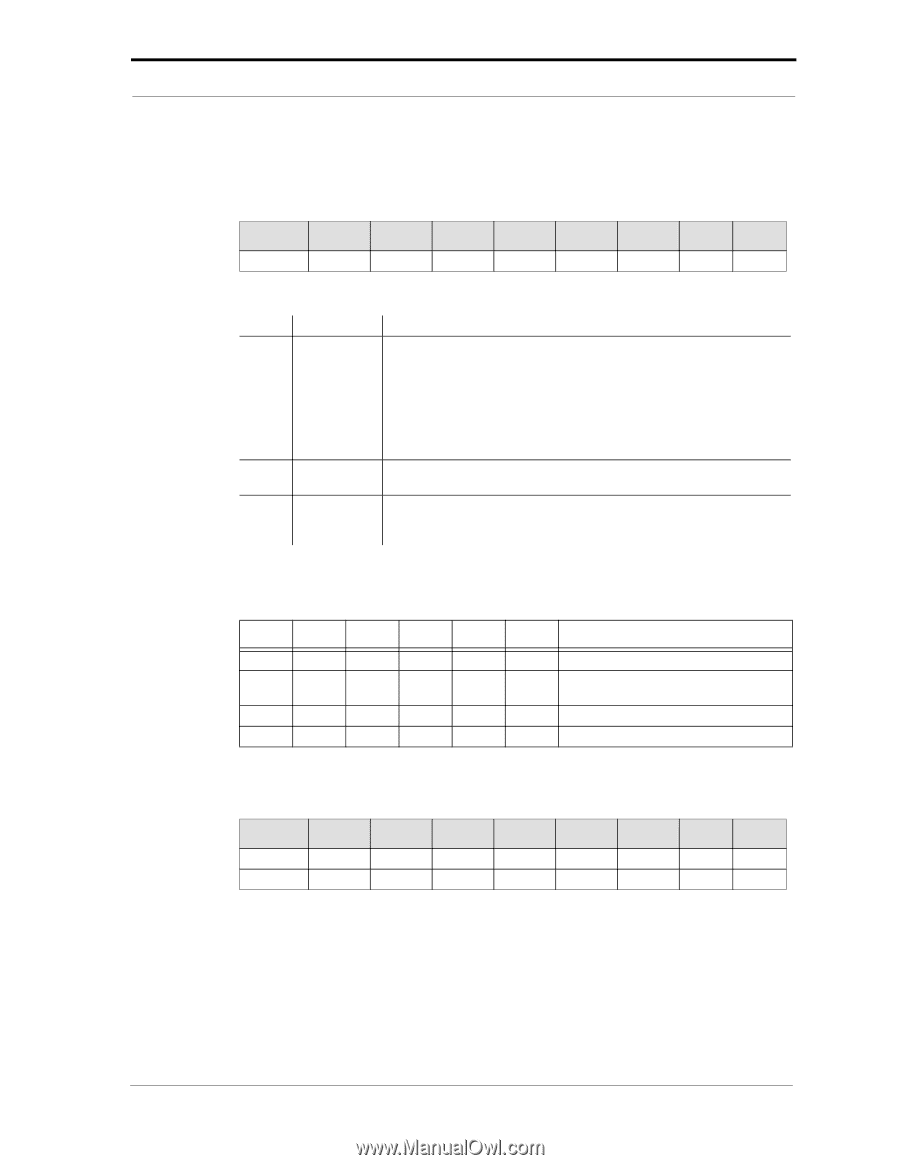
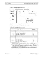
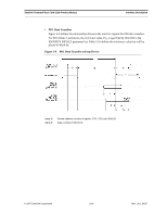
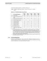
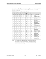
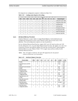
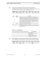
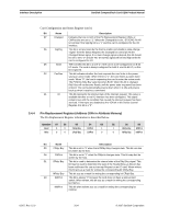
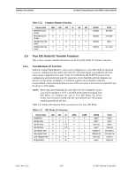
SanDisk CompactFlash Card OEM Product Manual Interface Description 3.4.2 Configuration Option Register (Address 200h in Attribute Memory) The Configuration Option Register is used to configure the card's interface, address decoding and interrupt and to issue a soft reset to the CompactFlash Memory Card. Operation R/W D7 SRESET D6 LevIREQ D5 Conf5 D4 Conf4 D3 Conf3 D2 Conf2 D1 Conf1 D0 Conf0 Bit D7 D6 D5-D0 Name SRESET LevIREQ Conf 5-Conf0 Description Setting this bit to one (1), waiting the minimum reset width time and returning to zero (0) places the card in the Reset state. Setting this bit to "1" is equivalent to assertion of the +RESET signal except that the SRESET bit is not cleared. Returning this bit to "0" leaves the card in the same un configured, Reset state as following power-up and hardware reset. This bit is set to "0" by power-up and hardware reset. Using the PCMCIA Soft Reset is considered a hard Reset by the ATA Commands. Contrast with Soft Reset in the Device Control Register. This bit is set to "1" when Level Mode Interrupt is selected, and"0" when Pulse Mode is selected. Set to "0" by Reset. Configuration Index. Set to "0" by reset. It's used to select operation mode of the card as shown below. NOTE: Conf5 and Conf4 are reserved and must be written as "0". Table 3-20 Card Configurations Conf5 0 0 0 0 Conf4 0 0 0 0 Conf3 0 0 0 0 Conf2 0 0 0 0 Conf1 0 0 1 1 Conf0 0 1 0 1 Disk Card Mode Memory Mapped I/O Mapped; any 16-byte system decoded boundary I/O Mapped; 1F0-1F7/3F6-3F7 I/O Mapped; 170-177/376-377 3.4.3 Card Configuration and Status Register (Address 202h in Attribute Memory) The Card Configuration and Status Register contain information about the card's condition. Operation D7 D6 D5 D4 Read Changed SigChg IOis8 0 Write 0 SigChg IOis8 0 D3 D2 D1 D0 0 PwrDwn Int 0 0 PwrDwn 0 0 © 2007 SanDisk Corporation 3-23 Rev. 12.0, 02/07
-
 1
1 -
2
-
3
-
4
-
5
-
6
-
7
-
8
-
9
-
10
-
11
-
12
-
13
-
14
-
15
-
16
-
17
-
18
-
19
-
20
-
21
-
22
-
23
-
24
-
25
-
26
-
27
-
28
-
29
-
30
-
31
-
32
-
33
-
34
-
35
-
 36
36 -
 37
37 -
 38
38 -
 39
39 -
 40
40 -
 41
41 -
 42
42 -
 43
43 -
 44
44 -
 45
45 -
 46
46 -
47
-
48
-
49
-
50
-
51
-
52
-
53
-
54
-
55
-
56
-
57
-
58
-
59
-
60
-
61
-
62
-
63
-
64
-
65
-
66
-
67
-
68
-
69
-
70
-
71
-
72
-
73
-
74
-
75
-
76
-
77
-
78
-
79
-
80
-
81
-
82
-
83
-
84
-
85
-
86
-
87
-
88
-
89
-
90
-
91
-
92
-
93
-
94
-
95
-
96
-
97
-
98
-
99
-
100
-
101
-
102
-
103
-
104
-
105
-
106
-
107
-
108
 |
 |