SanDisk SDCFH-004G Product Manual - Page 44
True IDE Mode I/O Transfer Function
 |
UPC - 878587001044
View all SanDisk SDCFH-004G manuals
Add to My Manuals
Save this manual to your list of manuals |
Page 44 highlights
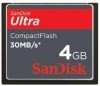
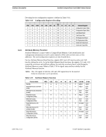
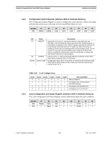
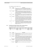
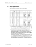
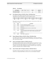
Interface Description SanDisk CompactFlash Card OEM Product Manual Table 3-22 Common Memory Function Function Code -REG -CE2 -CE1 A0 -OE -WE Word Read Access H L L X L H (16 bits) Word Write Access (16 bits) H L L X H L Odd Byte Read Only H L H X L H (8 bits) Odd Byte Write Only H L H X H L (8 bits) D15-D8 Odd Byte Odd Byte Odd Byte Odd Byte D7-D0 Even Byte Even Byte High Z Don't Care 3.6 True IDE Mode I/O Transfer Function This section contains valuable information on the True IDE Mode I/O Transfer function. 3.6.1 True IDE Mode I/O Function SanDisk CompactFlash Memory cards can be configured in a True IDE Mode of operation. Cards are configured in this mode only when the -OE input signal is grounded by the host when power is applied to the cards. In this True IDE Mode, the PCMCIA protocol and configuration are disabled and only I/O operations to the Task File and Data Register are allowed. In this mode, no Memory or Attribute registers are accessible to the host. CompactFlash cards permit 8-bit data accesses if the user issues a Set Feature Command to put the device in 8-bit Mode. NOTE: Removing and reinserting the card while the host computer's power is on will reconfigure it to PC Card ATA mode from the original True IDE Mode. To configure the card in True IDE Mode, the 50-pin socket must be power cycled with the card inserted and -OE (output enable) grounded by the host. Table 3-23 defines the function of the operations for the True IDE Mode. Table 3-23 IDE Mode I/O Function Function Code -CE2 -CE1 A0 Invalid Mode L L X Standby Mode H H X Task File Write H L 1.7h Task File Read H L 1-7h Data Register Write H L 0 Data Register Read H L 0 Control Register Write L H 6h Alt Status Read L H 6h -IORD X X H L H L H L -IOWR X X L H L H L H D15-D8 High Z High Z Don't care High Z Odd Byte in Odd Byte Out Don't Care High Z D7-D0 High Z High Z Data In Data Out Even Byte In Even Byte Out Control In Status Out 02/07, Rev. 12.0 3-26 © 2007 SanDisk Corporation
-
 1
1 -
2
-
3
-
4
-
5
-
6
-
7
-
8
-
9
-
10
-
11
-
12
-
13
-
14
-
15
-
16
-
17
-
18
-
19
-
20
-
21
-
22
-
23
-
24
-
25
-
26
-
27
-
28
-
29
-
30
-
31
-
32
-
33
-
34
-
35
-
36
-
37
-
38
-
 39
39 -
 40
40 -
 41
41 -
 42
42 -
 43
43 -
 44
44 -
 45
45 -
 46
46 -
 47
47 -
 48
48 -
 49
49 -
50
-
51
-
52
-
53
-
54
-
55
-
56
-
57
-
58
-
59
-
60
-
61
-
62
-
63
-
64
-
65
-
66
-
67
-
68
-
69
-
70
-
71
-
72
-
73
-
74
-
75
-
76
-
77
-
78
-
79
-
80
-
81
-
82
-
83
-
84
-
85
-
86
-
87
-
88
-
89
-
90
-
91
-
92
-
93
-
94
-
95
-
96
-
97
-
98
-
99
-
100
-
101
-
102
-
103
-
104
-
105
-
106
-
107
-
108
 |
 |