SanDisk SDCFH-004G Product Manual - Page 42
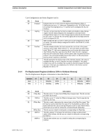
Pin Replacement Register Address 204h in Attribute Memory
 |
UPC - 878587001044
View all SanDisk SDCFH-004G manuals
Add to My Manuals
Save this manual to your list of manuals |
Page 42 highlights
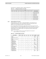
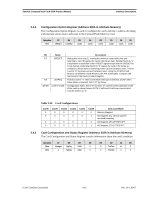
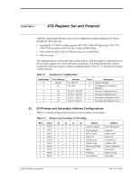
Interface Description SanDisk CompactFlash Card OEM Product Manual Card Configuration and Status Register (con't) Bit Name Description D7 Changed Indicates that one or both of the Pin Replacement Register CRdy, or CWProt bits are set to "1". When the Changed bit is set, -STSCHG Pin 46 is held low if the SigChg bit is a "1" and the card is configured for the I/O interface. D6 SigChg This bit is set and reset by the host to enable and disable a state-change "signal" from the Status Register, the Changed bit control pin 46 the Changed Status signal. If no state change signal is desired, this bit should be set to zero "0" and pin 46 (-STSCHG) signal will be held high while the card is configured for I/O D5 IOis8 The host sets this bit to a one "1" if the card is to be configured in an 8-bit I/O mode. The card is always configured for both 8- and 16-bit I/O, so this bit is ignored. D2 PwrDwn This bit indicates whether the host requests the card to be in the power saving or active mode. When the bit is "1", the card enters a power down mode. When "0", the host is requesting the card to enter the active mode. The PCMCIA Rdy/-Bsy value becomes BUSY when this bit is changed. Rdy/-Bsy will not become Ready until the power state requested has been entered. The card automatically powers down when it is idle and powers back up when it receives a command D1 Int This bit represents the internal state of the interrupt request. This value is available whether or not I/O interface has been configured. This signal remains true until the condition that caused the interrupt request has been serviced. If interrupts are disabled by the -IEN bit in the Device Control Register, this bit is a "0". 3.4.4 Pin Replacement Register (Address 204h in Attribute Memory) The Pin Replacement Register information is described below. Operation D7 D6 D5 D4 D3 Read 0 0 CRdy/-Bsy CWProt 1 Write 0 0 CRdy/-Bsy CWProt 0 D2 D1 D0 1 RRdy/-Bsy RWProt 0 MRdy/-Bsy MWProt Bit Name Description D5 CRdy/-Bsy This bit is set to "1" when the bit RRdy/-Bsy changes state. This bit can also be written by the host. D4 CWProt This bit is set to "1" when the RWprot changes state. This bit may also be written by the host. D1 RRdy/-Bsy This bit is used to determine the internal state of the Rdy/-Bsy signal. This bit may be used to determine the state of the Ready/-Busy as this pin has been reallocated for use as Interrupt Request on an I/O card. When written, this bit acts as a mask for writing the corresponding bit CRdy/-Bsy. MRdy/-Bsy This bit acts as a mask for writing the corresponding bit CRdy/-Bsy. D0 RWProt This bit is always "0" because the card does not have a write-protect switch. When written, this bit acts as a mask for writing the corresponding bit CWProt. MWProt This bit when written acts as a mask for writing the corresponding bit CWProt. 02/07, Rev. 12.0 3-24 © 2007 SanDisk Corporation
-
 1
1 -
2
-
3
-
4
-
5
-
6
-
7
-
8
-
9
-
10
-
11
-
12
-
13
-
14
-
15
-
16
-
17
-
18
-
19
-
20
-
21
-
22
-
23
-
24
-
25
-
26
-
27
-
28
-
29
-
30
-
31
-
32
-
33
-
34
-
35
-
36
-
 37
37 -
 38
38 -
 39
39 -
 40
40 -
 41
41 -
 42
42 -
 43
43 -
 44
44 -
 45
45 -
 46
46 -
 47
47 -
48
-
49
-
50
-
51
-
52
-
53
-
54
-
55
-
56
-
57
-
58
-
59
-
60
-
61
-
62
-
63
-
64
-
65
-
66
-
67
-
68
-
69
-
70
-
71
-
72
-
73
-
74
-
75
-
76
-
77
-
78
-
79
-
80
-
81
-
82
-
83
-
84
-
85
-
86
-
87
-
88
-
89
-
90
-
91
-
92
-
93
-
94
-
95
-
96
-
97
-
98
-
99
-
100
-
101
-
102
-
103
-
104
-
105
-
106
-
107
-
108
 |
 |