SanDisk SDCFH-004G Product Manual - Page 67
Word 164: CF Advanced PCMCIA I/O and Memory Timing Mode Capabilities and Set
 |
UPC - 878587001044
View all SanDisk SDCFH-004G manuals
Add to My Manuals
Save this manual to your list of manuals |
Page 67 highlights
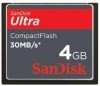
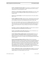
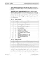
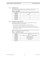
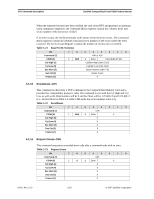
SanDisk CompactFlash Card OEM Product Manual ATA Command Description Word 164: CF Advanced PCMCIA I/O and Memory Timing Mode Capabilities and Settings. This word describes the capabilities and current settings for CFA defined advanced timing modes using the Memory and PCMCIA I/O interface. • Bits 2-0: Maximum Advanced PCMCIA I/O Mode Support Indicates the maximum I/O timing mode supported by the card. Value 0 1 2 3 4-7 Maximum PCMCIA I/O Timing Mode Supported 255 ns Cycle PCMCIA I/O Mode 120 ns Cycle PCMCIA I/O Mode 100 ns Cycle PCMCIA I/O Mode 80 ns Cycle PCMCIA I/O Mode Reserved • Bits 5-3: Maximum Memory Timing Mode Supported Indicates the Maximum Memory timing mode supported by the card. Value 0 1 2 3 4-7 Maximum Memory Timing Mode Supported 250 ns Cycle Memory Mode 120 ns Cycle Memory Mode 100 ns Cycle Memory Mode 80 ns Cycle Memory Mode Reserved • Bits 15-6: Reserved 5.1.6 Idle-97H, E3H This command causes the card to set BSY, enter the Idle (Read) mode, clear BSY and generate an interrupt. If the sector count is non-zero, it is interpreted as a timer count with each count being 5 milliseconds and the automatic power down mode is enabled. If the sector count is zero, the automatic power down mode is disabled. NOTE: This time base (5 msec) is different from the ATA specification. Table 5-13 Idle Bit Command (7) C/D/H (6) Cyl High (5) Cyl Low (4) Sec Num (3) Sec Cnt (2) Feature (1) 7 6 5 4 3 2 1 0 E3H or 97H X Drive X X X X Timer Count (5 ms increments) X © 2007 SanDisk Corporation 5-13 Rev. 12.0, 02/07
-
 1
1 -
2
-
3
-
4
-
5
-
6
-
7
-
8
-
9
-
10
-
11
-
12
-
13
-
14
-
15
-
16
-
17
-
18
-
19
-
20
-
21
-
22
-
23
-
24
-
25
-
26
-
27
-
28
-
29
-
30
-
31
-
32
-
33
-
34
-
35
-
36
-
37
-
38
-
39
-
40
-
41
-
42
-
43
-
44
-
45
-
46
-
47
-
48
-
49
-
50
-
51
-
52
-
53
-
54
-
55
-
56
-
57
-
58
-
59
-
60
-
61
-
 62
62 -
 63
63 -
 64
64 -
 65
65 -
 66
66 -
 67
67 -
 68
68 -
 69
69 -
 70
70 -
 71
71 -
 72
72 -
73
-
74
-
75
-
76
-
77
-
78
-
79
-
80
-
81
-
82
-
83
-
84
-
85
-
86
-
87
-
88
-
89
-
90
-
91
-
92
-
93
-
94
-
95
-
96
-
97
-
98
-
99
-
100
-
101
-
102
-
103
-
104
-
105
-
106
-
107
-
108
 |
 |