SanDisk SDCFH-004G Product Manual - Page 50
Cylinder Low LBA 15-8 Register Address-1F4[174]; Offset 4
 |
UPC - 878587001044
View all SanDisk SDCFH-004G manuals
Add to My Manuals
Save this manual to your list of manuals |
Page 50 highlights
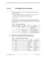
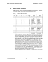
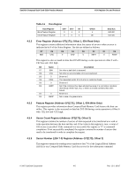
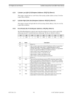
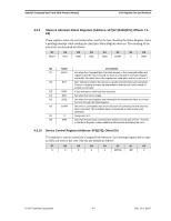
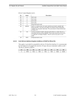
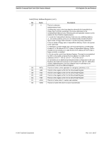
ATA Register Set and Protocol SanDisk CompactFlash Card OEM Product Manual 4.5.6 Cylinder Low (LBA 15-8) Register (Address-1F4[174]; Offset 4) This register contains the low order 8 bits of the starting cylinder address or bits 15-8 of the Logical Block Address. 4.5.7 Cylinder High (LBA 23-16) Register (Address-1F5[175]; Offset 5) This register contains the high order bits of the starting cylinder address or bits 23-16 of the Logical Block Address. 4.5.8 Drive/Head (LBA 27-24) Register (Address-1F6[176]; Offset 6) The Drive/Head Register is used to select the drive and head. It is also used to select LBA addressing instead of cylinder/head/sector addressing. The bits are defined as follows: D7 D6 D5 D4 D3 D2 D1 D0 1 LBA 1 DRV HS3 HS2 HS1 HS0 Bit Name Description D7 1 Bit set to 1. D6 LBA LBA is a flag to select either Cylinder/Head/Sector (CHS) or Logical Block Address Mode (LBA). When LBA=0, Cylinder/Head/Sector mode is selected. When LBA=1, Logical Block Address is selected. In Logical Block Mode, the Logical Block Address is interpreted as follows: LBA07-LBA00: Sector Number Register D7-D0. LBA15-LBA08: Cylinder Low Register D7-D0. LBA23-LBA16: Cylinder High Register D7-D0. LBA27-LBA24: Drive/Head Register bits HS3-HS0. D5 1 Bit set to 1. D4 DRV This bit will have the following meaning. DRV is the drive number. When DRV=0, drive (card) 0 is selected When DRV=1, drive (card) 1 is selected. The CompactFlash Card is set to be Card 0 or 1 using the copy field of the PCMCIA Socket & Copy configuration register. D3 HS3 When operating in the Cylinder , Head, Sector mode, this is bit 3 of the head number. It is Bit 27 in the Logical Block Address mode. D2 HS2 When operating in the Cylinder , Head, Sector mode, this is bit 2 of the head number. It is Bit 26 in the Logical Block Address mode. D1 HS1 When operating in the Cylinder , Head, Sector mode, this is bit 1 of the head number. It is Bit 25 in the Logical Block Address mode. D0 HS0 When operating in the Cylinder , Head, Sector mode, this is bit 0 of the head number. It is Bit 24 in the Logical Block Address mode. 02/07, Rev. 12.0 4-6 © 2007 SanDisk Corporation
-
 1
1 -
2
-
3
-
4
-
5
-
6
-
7
-
8
-
9
-
10
-
11
-
12
-
13
-
14
-
15
-
16
-
17
-
18
-
19
-
20
-
21
-
22
-
23
-
24
-
25
-
26
-
27
-
28
-
29
-
30
-
31
-
32
-
33
-
34
-
35
-
36
-
37
-
38
-
39
-
40
-
41
-
42
-
43
-
44
-
 45
45 -
 46
46 -
 47
47 -
 48
48 -
 49
49 -
 50
50 -
 51
51 -
 52
52 -
 53
53 -
 54
54 -
 55
55 -
56
-
57
-
58
-
59
-
60
-
61
-
62
-
63
-
64
-
65
-
66
-
67
-
68
-
69
-
70
-
71
-
72
-
73
-
74
-
75
-
76
-
77
-
78
-
79
-
80
-
81
-
82
-
83
-
84
-
85
-
86
-
87
-
88
-
89
-
90
-
91
-
92
-
93
-
94
-
95
-
96
-
97
-
98
-
99
-
100
-
101
-
102
-
103
-
104
-
105
-
106
-
107
-
108
 |
 |
