SanDisk SDCFH-004G Product Manual - Page 25
True IDE Mode, PC Card Memory Mode, PC Card I/O Mode, True IDE Mode, PC Card I/O Mode
 |
UPC - 878587001044
View all SanDisk SDCFH-004G manuals
Add to My Manuals
Save this manual to your list of manuals |
Page 25 highlights
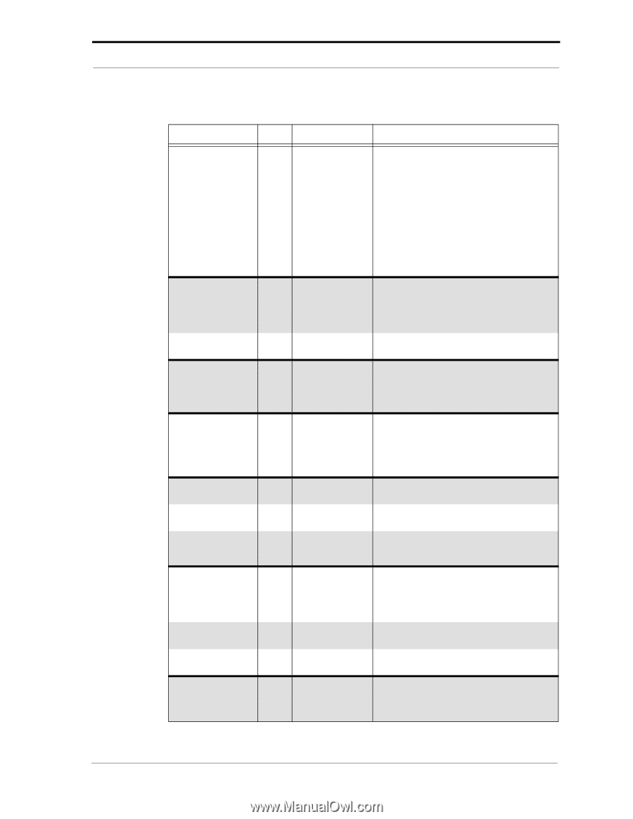
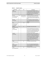
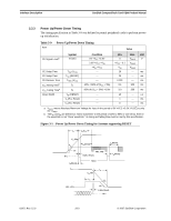
SanDisk CompactFlash Card OEM Product Manual Interface Description Table 3-4 Signal Description Signal Name Dir. Pin -DMACK (True IDE Mode) RESET I (PC Card Memory Mode) (PC Card I/O Mode) -RESET (True IDE Mode) VCC -- (PC Card Memory Mode) (PC Card I/O Mode) (True IDE Mode) -VS1 O -VS2 (PC Card Memory Mode) (PC Card I/O Mode) (True IDE Mode) -WAIT O (PC Card Memory Mode) -WAIT (PC Card I/O Mode) IORDY (True IDE Mode) -WE I (PC Card Memory Mode) -WE (PC Card I/O Mode) -WE (True IDE Mode) WP O (PC Card Memory Mode) 41 13, 38 33, 40 42 36 24 Description This signal is used by the host in response to DMARQ to initiate DMA transfers. NOTE: This signal may be negated by the host to suspend the DMS transfer in process. For Multiword DMA transfers, the device may negate DMARQ with the tL specified time once the DMACK- is asserted and reasserted again at a later time to resume DMA operation. Alternatively, if the device is able to continue the data transfer, the device may leave DMARQ asserted and wait for the host to reassert DMACK-. When the pin is high, this signal resets the card. The card is reset only at power-up if this pin is left high or open from power-up. The card is also reset when the Soft Reset bit in the Card Configuration Option Register is set. In the True IDE Mode this input pin is the active low hardware reset from the host. +5V, +3.3V power. Voltage Sense Signals. -VS1 is grounded so that the CompactFlash Card CIS can be read at 3.3 volts and VS2 is open and reserved by PCMCIA for a secondary voltage. SanDisk CompactFlash Memory cards do not assert the -WAIT signal. SanDisk CompactFlash Memory cards do not assert the -WAIT signal. SanDisk CompactFlash Memory cards, except when in UDMA modes, do not assert an IORDY signal. This is a signal driven by the host and used for strobing memory write data to the registers of the card when it is configured in the Memory Interface Mode. It is also used for writing the configuration registers. In PC Card I/O Mode, this signal is used for writing the configuration registers. In True IDE Mode this input signal is not used and should be connected to VCC by the host. Memory Mode-The CompactFlash Card does not have a write-protect switch. This signal is held low after the completion of the reset initialization sequence. © 2007 SanDisk Corporation 3-7 Rev. 12.0, 02/07
-
 1
1 -
2
-
3
-
4
-
5
-
6
-
7
-
8
-
9
-
10
-
11
-
12
-
13
-
14
-
15
-
16
-
17
-
18
-
19
-
 20
20 -
 21
21 -
 22
22 -
 23
23 -
 24
24 -
 25
25 -
 26
26 -
 27
27 -
 28
28 -
 29
29 -
 30
30 -
31
-
32
-
33
-
34
-
35
-
36
-
37
-
38
-
39
-
40
-
41
-
42
-
43
-
44
-
45
-
46
-
47
-
48
-
49
-
50
-
51
-
52
-
53
-
54
-
55
-
56
-
57
-
58
-
59
-
60
-
61
-
62
-
63
-
64
-
65
-
66
-
67
-
68
-
69
-
70
-
71
-
72
-
73
-
74
-
75
-
76
-
77
-
78
-
79
-
80
-
81
-
82
-
83
-
84
-
85
-
86
-
87
-
88
-
89
-
90
-
91
-
92
-
93
-
94
-
95
-
96
-
97
-
98
-
99
-
100
-
101
-
102
-
103
-
104
-
105
-
106
-
107
-
108
 |
 |