SanDisk SDCFH-004G Product Manual - Page 27
Table 3-6, Input Characteristics, Table 3-7, Output Drive Type, Table 3-8, Output Drive
 |
UPC - 878587001044
View all SanDisk SDCFH-004G manuals
Add to My Manuals
Save this manual to your list of manuals |
Page 27 highlights
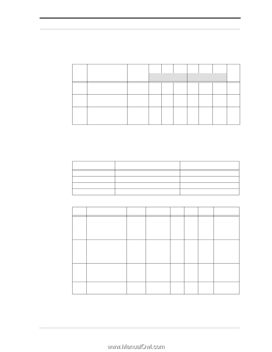
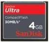
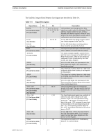
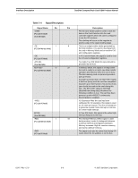
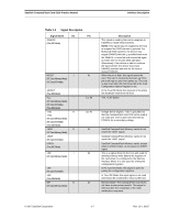
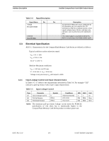
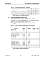
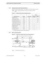
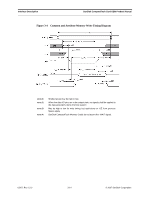
SanDisk CompactFlash Card OEM Product Manual Interface Description Table 3-6 defines the input characteristics of the parameters in Table 3-5. Table 3-6 Input Characteristics Type 1 2 3 Parameter Input Voltage CMOS Input Voltage CMOS Input Voltage CMOS Schmitt Trigger Symbol Vih Vil Vih Vil Vth Vtl Min. Typ. Max. Min. Typ. Max. VCC = 3.3V VCC = 5.0V Unit 2.4 4.0 V 0.6 0.8 1.5 2.0 V 0.6 0.8 1.8 2.8 V 1.0 2.0 3.3.2 Output Drive Type and Characteristics In Table 3-7 "x" refers to the characteristics described in Table 3-8. For example-"OT3" refers to Totempole output with a Type 3 output drive characteristic. Table 3-7 Output Drive Type Type OTx OZx OPx ONx Output Type Totempole Tri-state N-P Channel P-Channel Only N-Channel Only Valid Conditions loh & lol loh & lol loh only loh Only Table 3-8 Output Drive Characteristics Type Parameter Symbol Conditions Min. Typ. Max. Unit 1 Output Voltage Voh loh= -4 mA VCC V -0.8V Vol lol= 4 mA Gnd +0.4V 2 Output Voltage Voh loh= -8 mA VCC V -0.8V Vol lol= 8 mA Gnd +0.4V 3 Output Voltage Voh loh= -8 mA VCC V Vol lol= 8 mA -0.8V Gnd +0.4V X Tri-State Leakage Current loz Vol = Gnd -10 Voh = VCC 10 uA © 2007 SanDisk Corporation 3-9 Rev. 12.0, 02/07
-
 1
1 -
2
-
3
-
4
-
5
-
6
-
7
-
8
-
9
-
10
-
11
-
12
-
13
-
14
-
15
-
16
-
17
-
18
-
19
-
20
-
21
-
 22
22 -
 23
23 -
 24
24 -
 25
25 -
 26
26 -
 27
27 -
 28
28 -
 29
29 -
 30
30 -
 31
31 -
 32
32 -
33
-
34
-
35
-
36
-
37
-
38
-
39
-
40
-
41
-
42
-
43
-
44
-
45
-
46
-
47
-
48
-
49
-
50
-
51
-
52
-
53
-
54
-
55
-
56
-
57
-
58
-
59
-
60
-
61
-
62
-
63
-
64
-
65
-
66
-
67
-
68
-
69
-
70
-
71
-
72
-
73
-
74
-
75
-
76
-
77
-
78
-
79
-
80
-
81
-
82
-
83
-
84
-
85
-
86
-
87
-
88
-
89
-
90
-
91
-
92
-
93
-
94
-
95
-
96
-
97
-
98
-
99
-
100
-
101
-
102
-
103
-
104
-
105
-
106
-
107
-
108
 |
 |