SanDisk SDCFH-004G Product Manual - Page 28
Table 3-9, Power Up/Power Down Timing, Power Up/Power Down Timing for Systems supporting
 |
UPC - 878587001044
View all SanDisk SDCFH-004G manuals
Add to My Manuals
Save this manual to your list of manuals |
Page 28 highlights
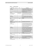
Interface Description SanDisk CompactFlash Card OEM Product Manual 3.3.3 Power Up/Power Down Timing The timing specification in Table 3-9 was defined to permit peripheral cards to perform powerup initialization. Table 3-9 Power Up/Power Down Timing Item Value CE Signal Levela CE Setup Time CE Setup Time CE Recover Time VCC Rising Timeb VCC Falling Timeb Reset Width Symbol Vi (CE) TSU (VCC) TSU (RESET) TREC (VCC) tpr tpf TW (RESET) Th (Hi-z Reset) TS (Hi-z Reset) Condition 0V
-
 1
1 -
2
-
3
-
4
-
5
-
6
-
7
-
8
-
9
-
10
-
11
-
12
-
13
-
14
-
15
-
16
-
17
-
18
-
19
-
20
-
21
-
22
-
 23
23 -
 24
24 -
 25
25 -
 26
26 -
 27
27 -
 28
28 -
 29
29 -
 30
30 -
 31
31 -
 32
32 -
 33
33 -
34
-
35
-
36
-
37
-
38
-
39
-
40
-
41
-
42
-
43
-
44
-
45
-
46
-
47
-
48
-
49
-
50
-
51
-
52
-
53
-
54
-
55
-
56
-
57
-
58
-
59
-
60
-
61
-
62
-
63
-
64
-
65
-
66
-
67
-
68
-
69
-
70
-
71
-
72
-
73
-
74
-
75
-
76
-
77
-
78
-
79
-
80
-
81
-
82
-
83
-
84
-
85
-
86
-
87
-
88
-
89
-
90
-
91
-
92
-
93
-
94
-
95
-
96
-
97
-
98
-
99
-
100
-
101
-
102
-
103
-
104
-
105
-
106
-
107
-
108
 |
 |
---
---
---
---
---
---
---
---
---
---
---
---
Interface Description
SanDisk CompactFlash Card OEM Product Manual
3.3.3
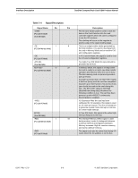
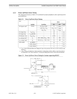
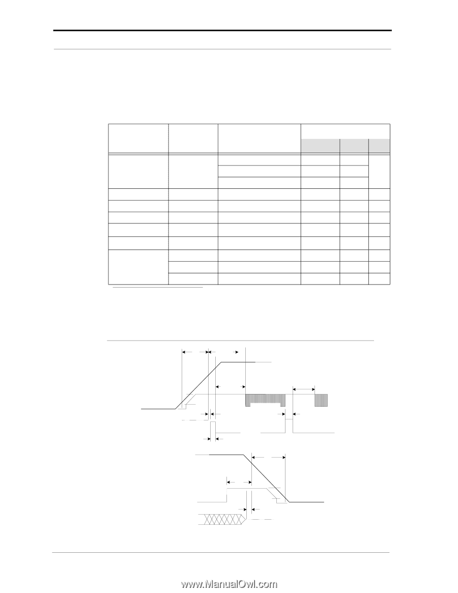
Power Up/Power Down Timing
The timing specification in Table 3-9 was defined to permit peripheral cards to perform power-
up initialization.
Table 3-9
Power Up/Power Down Timing
Item
Value
Symbol
Condition
Vi (CE)
0V <V
CC
<2.0V
0
V
iMAX
CE Signal Level
a
2.0V <V
CC
<V
IH
<V
CC
- 0.1
V
iMAX
<V
IH
<V
CC
V
IH
V
iMAX
CE Setup Time
20
ms
T
SU
(V
CC)
CE Setup Time
T
SU
(RESET)
20
ms
CE Recover Time
0.001
ms
T
REC
(V
CC)
10%-->90% of (V
CC
+ 5%)
0.1
300
ms
t
pr
V
CC
Rising Time
b
90% of (V
CC
+ 5%)-->10%
3.0
300
ms
t
pf
V
CC
Falling Time
b
Reset Width
T
W
(RESET)
10
µ
s
T
h
(Hi-z Reset)
1
ms
T
S
(Hi-z Reset)
0
ms
Min.
Max.
Unit
a. V
iMAX
means Absolute Maximum Voltage for Input in the period of 0V <VCC <2.0V, Vi (CE) is only
0V~V
iMAX
.
b. The t
pr
and t
pf
are defined as "linear waveform" in the period of 10% to 90% or vice-versa. Even if
the waveform is not "linear waveform," its rising and falling time must be met by this specification.
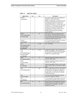
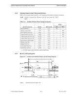
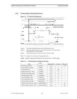
Figure 3-1
Power Up/Power Down Timing for Systems supporting RESET
V
CC
2V
V
IH
V
CC
Min.
t
rec
-CE1, -CE2
ts (Hi-z Reset)
Hi-z
t
pf
t
W
(Reset)
V
CC
Min.
t
W
(Reset)
Reset
t
pr
t
SU
(V
CC
)
-CE1, -CE2
t
SU
(Reset)
t
SU
(Reset)
th (Hi-z Reset)
Hi-z
2V
V
IH
02/07, Rev. 12.0
3-10
© 2007 SanDisk Corporation
V