SanDisk SDCFH-004G Product Manual - Page 38
Card Configuration
 |
UPC - 878587001044
View all SanDisk SDCFH-004G manuals
Add to My Manuals
Save this manual to your list of manuals |
Page 38 highlights
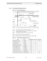
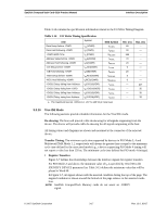
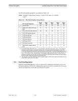
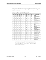
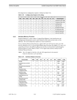
Interface Description SanDisk CompactFlash Card OEM Product Manual The PIO data transfer parameters are defined in Table 3-16. NOTE: SanDisk CompactFlash Memory cards do not assert an -IORDY signal. Table 3-16 PIO Data Transfer to/from Device PIO Timing Parameters t0a Cycle time (min.) t1 Address valid to IORD-/IOWR- setup (min.) t2a IORD-/IOWR- pulse width 16-bit (min.) t2ia IORD-/IOWR- recovery time (min.) t3 IOWR- data setup (min.) t4 IOWR- data hold (min.) t5 IORD- data setup (min.) t6 IORD- data hold (min.) t6zb IORD- data tri-state (max.) t9 IORD-/IOWR- to address valid hold (min.) Mode 0 (ns) 600 70 165 --60 30 50 5 30 20 Mode 1 (ns) 383 50 125 --45 20 35 5 30 15 Mode 2 (ns) 240 30 100 --30 15 20 5 30 10 Mode 3 (ns) 180 30 80 70 30 10 20 5 30 10 Mode 4 (ns) 120 25 70 25 20 10 20 5 30 10 a. t0 is the minimum total cycle time, t2 is the minimum command active time, and t2i is the minimum command recovery time or command inactive time. The actual cycle time equals the sum of the actual command active time and the actual command inactive time. The three timing requirements of t0, t2, and t2i shall be met. The minimum total cycle time requirements are greater than the sum of t2 and t2i. This means a host implementation may lengthen either or both t2 or t2i to ensure that t0 is equal to or greater than the value reported in the devices IDENTIFY DEVICE data. A device imple mentation shall support any legal host implementation. b. This parameter specifies the time from the negation edge of /IORD to the time that the data bus is no longer driven by the device (tri-state). 3.4 Card Configuration SanDisk CompactFlash Memory cards are identified by appropriate information in the Card Information Structure (CIS). The configuration registers are used to coordinate the I/O spaces and the interrupt level of cards that are located in the system. 02/07, Rev. 12.0 3-20 © 2007 SanDisk Corporation
-
 1
1 -
2
-
3
-
4
-
5
-
6
-
7
-
8
-
9
-
10
-
11
-
12
-
13
-
14
-
15
-
16
-
17
-
18
-
19
-
20
-
21
-
22
-
23
-
24
-
25
-
26
-
27
-
28
-
29
-
30
-
31
-
32
-
 33
33 -
 34
34 -
 35
35 -
 36
36 -
 37
37 -
 38
38 -
 39
39 -
 40
40 -
 41
41 -
 42
42 -
 43
43 -
44
-
45
-
46
-
47
-
48
-
49
-
50
-
51
-
52
-
53
-
54
-
55
-
56
-
57
-
58
-
59
-
60
-
61
-
62
-
63
-
64
-
65
-
66
-
67
-
68
-
69
-
70
-
71
-
72
-
73
-
74
-
75
-
76
-
77
-
78
-
79
-
80
-
81
-
82
-
83
-
84
-
85
-
86
-
87
-
88
-
89
-
90
-
91
-
92
-
93
-
94
-
95
-
96
-
97
-
98
-
99
-
100
-
101
-
102
-
103
-
104
-
105
-
106
-
107
-
108
 |
 |